What can be accomplished with just a torch and compressed air? We can think of many things, but bringing a 17-foot-long marine shaft into ±.002 in tolerance was not on our list.
Heat straightening (PDF) utilizes an oxy-acetylene flame that is used to quickly heat a small section of a workpiece. As the metal cools, it contracts more than it expanded when heated, resulting in a changed volume. With skill, any distortions on a shaft can theoretically be straightened out with enough time (and oxy-acetylene). Heat straightening is commonly applied to steel but works on nickel, copper, brass and aluminum additionally.
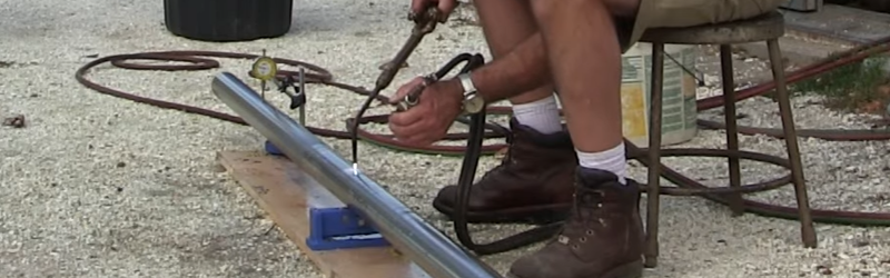
[Keith Fenner’s] standard process for trueing stock is sensitive enough that even sunlight can introduce irregularities, but at the same time is robust enough to carry out in your driveway. However, even though the only specialty tools you need are a torch, compressed air and work supports, watching [Keith] work makes it clear that heat straightening is as much an art as it is a science. Check out his artistry in the video below the break.
[Keith] is not new here. We’re big fans of [Keith’s] YouTube channel; he works on everything from harpoons to sailboats and has more experience than you could shake a stick at. In addition to the big ticket item, we enjoyed watching [Keith] remove a thoroughly stuck 3 in nut with only a hammer. Not working on 17 ft marine shafts? This DIY surface grinder might be something you can roll with.


My father-in-law, now in his mid nineties owned a marina and was a practitioner of this black art. By the time I met my wife, the shop was no longer offering the service as the price they had to charge for the time required became greater than the cost of new shafts, but I did watch him do one once for a beautiful old teak motor launch whose owner was a stickler for orginal parts.
People who weld up homebuilt airplanes from steel tubing and then cover them with fabric end up doing this to straighten the frame during the welding process, albeit not quite to those tolerances. It’s useful to know generally how to do it if you’re involved with fabrication.
NOE course plotting pilots for special deliveries !
I winced watching him hammer on the jaws of his lathe…
it was like seeing some dude kicked in the balls…
I foresee a video about shimming bearings in his future.
It’s a rawhide mallet.
I would have winced if it were a novice going ape on an import quality mini lathe…
But he’s not a novice, used minimal and carefully directed force, and that is a literally massive back-plate he’s working against….
That ole’ Clausing didn’t even feel it. :-)
They also use this technique to straighten out bridge girders that have been damaged.
I have a 1/4″ aluminum build plate for my 3d printer that is slightly warped. If I break out my acetylene plumber’s torch, what are the odds I can make it flat? Does anyone know if this would be a waste of time and money?
Normally, getting a good machinist to surface and square up the part is the best option.
Crude wet-sanding on a flat surface in a figure-eight pattern may take out the high spots for you.
When you cut/drill/heat most metals it will cause slight warping, and this is one reason a CNC mill does a roughing pass with coolant on parts.
Yeah, I agree with OLD_HACK. Wet Sanding is the best idea. Not sure if you have another flat surface, but perhaps a cheap piece of plate glass as the backing for sandpaper would work. How out of true is the piece? <0.5mm?
I think a square plate is going to act in unpredictable ways if you heat and cool it – I think it's a much more complicated shape to work with compared with the bar stock in this video. You risk making it pringle.
yes
If you break out the acetylene, there’s good chance of a hole burnt through :P
But on a more serious note, if the plate was hardened, you’ll screw up the hardening (which might result in unpredictable warping/bending), doesn’t take all that much heat to do it for aluminium…
I’d rather recommend a soft mallet and something soft-ish to put the workpiece on, then just bash it into being straight…
Even if you break out the acetylene you’d have to go ape on the thing to burn a hole in it, since aluminum has a high thermal conductivity. Throwing the oxygen lever on the cutting torch might yield a different result.
Also, for the record, I agree that having it trued up at a machine shop it the best course you can take.
” then just bash it into being straight…”
Mike Pence, is that you?!?
As my uncle taught me…
“When in doubt, hit it with a hammer, if that doesn’t work, use a bigger hammer.
If it brakes, you needed a new one anyway.”
That’s great stuff me. :-)
Aluminum is more difficult to use this method on because of high thermal conductivity prevents localized thermal effects from occurring. Also, this method depends on being able to heat-soften the material which, for aluminum, is just a few degrees below melting. Heating will also allow relaxation of uneven tension inside the material due to the rolling process (betting that it isn’t MIC-6 cast plate) which will warp it even more.
Give it a try and let us know what happens.
Nice. Wonder if some shade would help with his “sun” problem.
You’re right. He doesn’t have a sun problem. He has a shop’s-too-damn-small problem. :-)
Yes he has. Have you ever seen the hole in his wall so he can stick a shaft in his lathe?
I’d think it would be difficult to find a machine shop that does NOT have hole in the wall in line with at least one lathe’s spindle
I’ve got a friend who can do this. Perfected the art on piping for boilers at power plants.
Another black art he perfected was dent removal under pressure. Literally, weld an airtight seal on both ends of a pipe, along with a pressure valve, and pump a couple thou’ of shielding gas inside the pipe, then sloooowly heat the dent and let the pressure push it out.
If I hadn’t seen him do this multiple times, and seen the results be tested in every damn way known to the regulators in charge of such equipment, I wouldn’t have believed it could be done to an acceptable tolerance, much less the tolerances they use.
This was generally done on finished assemblies worth $10K+ it was worth having him take the time to do this. Or on super long pipes that had become bent.
That’s terrifying
That’s art.
All of the above!
I just realized, he would have punched me for this comment. TUBING. Not piping. There’s a difference.
What is the difference, exactly?
Think Swagelok-style tubing, vs cast iron threaded piping. I can’t remember the explicit definition, but that was a differentiation that was heavily emphasized when we were trained up on Swagelok at work.
Swagelok guys do not like it at all when you refer to their tubes as piping!
Apparently Tubing is measured by OD and wall thickness with rather close tolerances ( a notable exception is copper tube which is 1/8″ over the listed diameter) while pipe is measured by nominal OD and schedule.
The dimensional measurements are the most obvious difference. The primary difference for boiler techs though is that pipe has a seam. Proper tubes don’t. Pipes are made from sheet stock being folded, and then having the seam welded or brazed together. Tubes are extruded, no seams along the length, only welds where two tubes meet.
Ship builders are use these techniques to shape hull plates. Just a much bigger torch.
and water cooling to keep the plate from baking them alive :D
Baking + insufficient water cooling = steam cooking!
Baking is radiative heat transfer, which is usually < steaming, which is a contact heat transfer. So, if you need to cool something down, make sure you know for sure you have enough of cold water to do it.
Can be seen here:
https://youtu.be/Ec4yuYzEZZM?t=328
If you’re interested in Japan in general or (especially) visiting Japan, you’ll get a lot out of the Japanology series.
Jump to 5:30. I tried to ‘copy link at time’ but it didn’t work.
I work as a machinist, and while I can see the technique here,
I can’t possibly see how he’s accurately measuring run out like
this.
He’s using a dial indicator on a shaft that supported an arbitrary
distance from the board and it’s a wooden board. That board
Would have to be perfectly flat and perfectly stiff and those rollers
Exactly the same distance from that board face for him to use an indicator
In such a simple manner to test the circular run out the way he is.
I’m not calling bull on this he obviously makes a living doing it,
but I fail to see how someone can accurately test run-out between centers
using a setup like this on what is most likely a warped board on unflat ground.
People normally do this sort of thing on a granite surface plate with v blocks made of precision ground steel to test circular runout at this level of accuracy.
It might be one thing if he was checking for quarter inches, but there’s no way that board is actually flat to within even a half a thousandth the entire length. I mean it’s just physically impossible for wood to actually be that flat and stay that flat to simply measure with an indicator like that, and expect their measurement is colinear. Can someone please comment on this? I do like his technique for soft jaws though
It doesn’t matter if the board is flat. As long as the indicator and roller don’t move, the indicator will always show the offset from the roller to the indicator.
With the shaft resting on the supports, it’s going to bend in the middle by its own weight, but if it’s straight and you spin it, it won’t wobble because every time it turns around it sags the same amount on that side. If it’s not straight then you’ll see it go up and down a little.
So it doesn’t matter which way you offset the indicator, because you’re not looking at the absolute deflection – you’re looking for the wobble.
That said, the technique is actually changing the hardness/stiffness of the steel by heat and cold, so when it’s loaded by gravity it bends more on one side than the other and -that- straightens it out, and that’s what the guy is really measuring. He’s not really straightening it up at the micron level because when you take the load off the shaft is going to spring to a different shape. It might be originally bent like a U but when you modify the springyness of each side of the shaft and put it horizontally on supports, the U straightens out. That also means if the bearing blocks are not in the same place in the boat the shaft isn’t really going to turn straight to within 0.02 beacuse the loading is different.
The technique works because the hardness of the material is only being modified on the surface, not right through the part. There is a related process called Stress-Peen Straightening that works the same way by forcing the surface of the material into compression by work hardening accomplished by blasting with a highly controlled stream of steel shot.
He has another video where he takes a hammer to peen the surface of a shaft to straighten it out.
The write up is misleading. The shaft is not being made straight. That’s impossible with the setup used as there is no reference for straightness. What’s being done is removing run-out at the ends of the shaft. For that one only needs two supports placed at the same points on the shaft as the bearings in which it runs. It’s also why there are only two bearing to support a shaft. The engine end of the shaft will be fitted with a coupler to allow some run-out so as to avoid engine bearing damage. The prop end simply needs the run-out reduced to the point that it does not produce excessive vibration.
It’s worth noting that the process leaves residual stresses in the shaft which will eventually result in strains. So there are definite limits to how far you can go with such a method. The same thing applies to straightening shafts in an hydraulic press. After you stop, it will keep moving for a long time.
So what? Take any metal component from a machine that has been in service for any length of time and you will find it full of stresses, and that includes shafts like this where the runouts were within acceptable values on removal. Shafts reworked with this and similar techniques can and are reinstalled and provide hours of service without any creating any other issues.
.002
Ahh, you mean 0,05 mm
The original tolerance was 1/3,960,000th of a furlong. We translated into decimal inches to make it clearer to our international audience.
And I wondered what you mean with “+-0.002 in tolerance” as the +- declared a tolerance already… :D.
50,8 µm that is.
HAve seen this done on car axles too to either straighten out allignment issues, or on rally cars, introduce negative camber. (its heavy on the splines as there not running true but advantage is more grip in corners.)
another “trick” is to run mig weld beads around one half, as the bead cools and contracts it bends the tube.
The mig weld bead tip is also useful for taking out taper-bearing outer races.
It’s also annoying for welding handrails. People will weld just the bottom of the top portion (as you would expect) but don’t think about the weld distortion and the whole rail looks like it is sagging.
Sorry I’m skeptical about Mr. Fenner’s fussiness about “setting a standard and never settling” in this instance. The shafting is going to be exposed to varying temperatures all it’s life so I’m confused about the emphasis place on having a steady temperature at the initial inspection and tuning. The equipment the shaft will be placed isn’t going to be aligned all the time either. That’s why self aligning bearings where invented. Most of my life’s work experience has been in the Kansas oilfield where equipment is subject to outdoor temperatures as low as -40 F. and high as 130F. I have no doubt the marine environment is similarly variable.