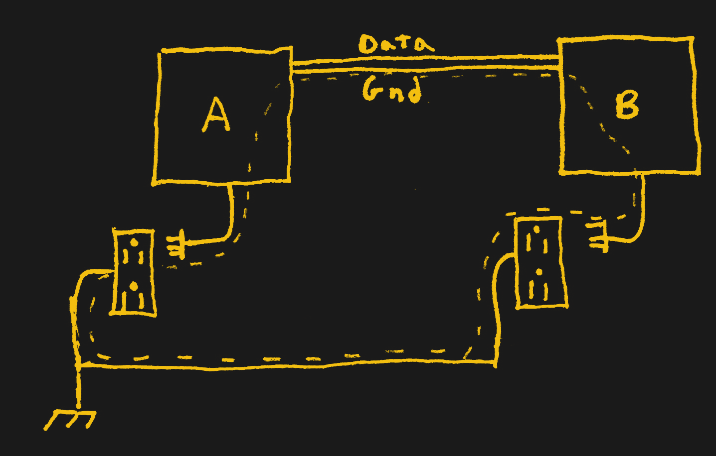
These magical creatures crop up out of nowhere and fry your electronics or annoy your ear holes. Understanding them will doubtless save you money and hassle. The ground loop in a nutshell is what happens when two separate devices (A and B) are connected to ground separately, and then also connected to each other through some kind of communication cable with a ground, creating a loop. This provides two separate paths to ground (B can go through its own connection to ground or it can go through the ground of the cable to A and then to A’s ground), and means that current may start flowing in unanticipated ways. This is particularly noticeable in analog AV setups, where the result is audio hum or visible bars in a picture, but is also sometimes the cause of unexplained equipment failures.
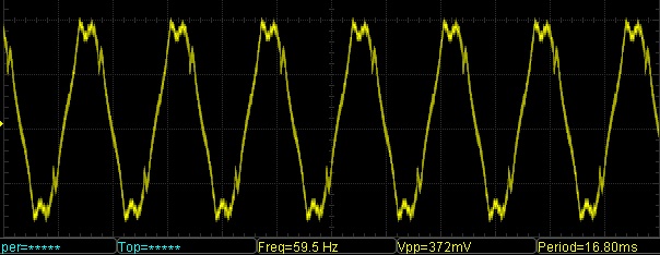
One example is your cable TV. This is an analog signal that comes into your house and is grounded to earth in one place, usually outside your house. The cable snakes its way to your entertainment center, where it plugs into your receiver, which is grounded to earth in a different place. This creates a loop, and, through electromagnetic induction coupled to all kinds of AC signals around, a stray current which then leaks through various circuits. Another way to think of it is as one half of a transformer; it’s a single loop and a good portion of that loop is right next to the live wire of the building power with a constantly changing current. It’s not uncommon for there to be a 50 or 60 hertz hum in audio equipment thanks to the effects of ground loops.
The Solution
Now that you’re an expert, solving the problem (or avoiding it entirely), is pretty straightforward. The most certain way is to cut the loop, which means removing the cable, or replacing it with something that isn’t a wire. You could switch to a wireless communication, like Bluetooth or WiFi. Some wired protocols use differential signals instead of single-ended signaling so that there isn’t a need for a common ground for reference. Move plugs around so that they are plugged into the same outlet, making your loop as small as possible. Another option is to use an isolator, which you could purchase for your cable of choice or design into your project with an optoisolator or isolation transformer. Do not use a cheater plug or remove the ground pin, as that just eliminates a safety feature and could create a dangerous situation with a chassis at live voltage.
When it comes to your oscilloscope, it’s likely that you will at some point want to probe something that is powered by mains, and then you get a completely different kind of ground loop. If your thing is battery powered, there’s no danger here; go nuts because there is no way to create a ground loop. If it’s plugged in to the wall but through an isolated power supply (something with only two prongs and an isolation transformer), you’re still ok, because there’s still no path for a ground loop, but you may see some noise from dirty power.
But if it’s connected to mains and has an earth pin (even indirectly, like a device powered by USB through a computer power supply), there is the potential to create a ground loop, because you’re connecting your grounded scope to another grounded device via the probe. The ground clip on the probe is connected straight to the ground pin, and the grounds on all the probes are connected to each other, and those ground pins are connected to the ground on your device. If that wasn’t clear, it’s better summed up as “all your grounds are already connected to each other and referenced to the same wire – the ground pin.” When you connect the ground clip to the device under test, you create a ground loop, which will add noise to your measurement and possibly hurt the scope.
If you get it wrong and attach the ground clip to something that’s not actually ground, then you’ll have all kinds of problems as the device is now shorted to a ground through your probe, which will quickly self-destruct. Testing devices that have a ground pin requires extra special care to prevent connecting things at different potentials. Breaking the ground loop is possible by simply not connecting the ground clip, though this has other consequences. Here, best practices are to use differential probes or hook the device under test up to an isolation transformer. Do not remove the grounding from your scope, though, because you will be touching it frequently, and it’s best that you don’t get shocked.
So to sum up: ground isn’t just ground. For measurement noise purposes, it’s best for each device to have one and only one path to a single ground point. When there are two or more paths to ground, they can form a loop that will pick up all sorts of environmental electrical and magentic interference. Fixing a ground loop is as simple as breaking it open, but to do so you have to have a good mental picture of all of the ground paths in play. What’s the trickiest ground loop that you’ve ever seen? Are we missing any good solutions?


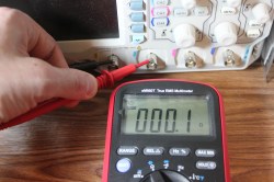
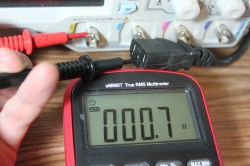
“The scope probe grounds are connected. ”
multimeter?
They’re testing continuity between the two probe grounds, and between the probe grounds and the ground pin. With a multimeter.
there is another way to fix a gound loop prob i have milatery genarator requires a grounding rod, probem doing so makes dag on lot noise on ground line, so how can i have bouth people say remove the grounding wire, this not a option, so dose any one have a right respons the even a elec company would not compain about, ? i use a 3 phase filter it breaks each line all lines even the ground this filters all lines, there for there is no direct path to ground and no ground loop, now most people most people that go school would never know to do this, in fack i use 3 phaase filters to proteck my servers. from emp hits from when substation gose down when they reconect it emp suge sent throw lines, why things gose out, such filters blocks emp and surges, duke engery ack appoved of genarator set up throw one has never been set up in such a way, it would well pass any codes, i would advise one thing no one went to school will do this, as they have no clue why, they never train. also if u know nothing about wireing codes stay away from doing it it can kill u if u get to small of a fillter, or worse yeat can distroy your genarator, for a 10kw gen u need a 150 amp 3 phase filter min, and i would to advise a 150 amp gfi on it
Mate, I just got eye cancer just from reading this.
Haha the perfect comment, I’m dying laughing!!
I have to say that a person who went to school would at least be able to convey their message without having their reader stumbling on every other word!
Yeah that was a rough read – couldn’t make it past a couple lines. My brain and eyes hurt
Your disdain for schooling might need toning down so that you can work on conveying your thoughts more clearly.
Thanks for this. I’ve dealt with them before but never looked up the reason behind it.
I mostly use a TekScope and that has isolated inputs on the probes. This means you can see differential signals without A-B but it also means that when I am forced to use one of my other scopes or someone else’s scope I am in grave danger of doing something stupid. After 20 years it is a hard habit to break.
The correct way to resolve it, in the simple example presented above, is *not* to disconnect any mains earths, but to disconnect the shield of the signal cable at one end (either the A end or the B end) of the cable.
+10000
But then if either A or B loses ground and starts floating, you get a massive surge of current right through the signal wire and destroy your devices.
That’s why “grounding” is tricky. A and B have to be grounded properly. If the shield is carrying “a massive surge of current” it’s going to cause issues with your devices too.
Yeah, but it will only be carrying the current while the charges equalize. There’s nothing in the ground wiring to get hurt, so the issue is just a temporary glitch.
Imagine for example someone kicks the power cord of your equipment off the wall. That breaks the ground and suddenly your device is left floating against the potential in the signal wire. Then you go plug it back in and *zap* you just killed your stereos.
Years ago I had hum in my audio system through my cable box (I don’t use this setup anymore), my solution was to run a ground wire from the cable splitter housing to the outside of a receptacle box near the splitter. Was this incorrect? It certainly got rid of the hum.
Tom, I have solved similar issues by running jumpers from every “source” to one point on the reciever/pre-amp…it may not by technically correct but it works by ensuring that ground is at the same level across the system.
Adding the external ground wires (especially in a star pattern like Dr. Rockzo) is a good solution for an audio setup. The wires can provide a return path to ground that could be lower impedance than the signal shield. The star pattern (single point to many points) can break the ground loop.
Well the safety earth should be correctly and reliably wired right from the start.
You could also just wrap ferrites around the cable. For high-frequency applications that’s usually good enough, and it’s the reason why you see ferrite cores wrapped around virtually every kind of signal cable you can imagine.
You can still end up having a low-frequency loop antenna, but that’s easy to filter out if you’re in the MHz range or higher. Harder obviously if you’re in audio, where cutting the shield can be effective.
Uhm… 50/60Hz aren’t really high-frequency noises. ferrites are useless in case of a ground loop
“Uhm… 50/60Hz aren’t really high-frequency noises.”
Sorry, maybe you misunderstood. The only reason you care about 50/60 Hz noise is if your *passband* includes 50/60 Hz – like in audio. If you passband *doesn’t* include 50/60 Hz, like, say, in RF applications, or VGA, or HDMI, or USB, then you just strap a ferrite onto the wire to keep out higher-frequency signals, and your passband filter takes care of the 50/60 Hz noise.
This is why the effect of multiple ground connections is for the most part ignored in RF applications if the passband doesn’t extend down too close to ~DC.
“ferrites are useless in case of a ground loop”
Ferrites are useless for *low frequency* effects of a ground loop. Loops don’t just pick up low frequency though – in general they’re *better* at ~10s-100s of kHz because they’re a better match, and ferrites can easily load down *that* portion.
Between that and using “star” grounds, you prevent 90%+ of your problems. Plus twisted pairs are more effective than shields at preventing RFI
In my case, using DOUBLE SHIELDED MALE TO MALE phono cables (FOS in this case, with a single signal wire) between turntable and receiver, and DISCONNECTING the ground wire between them, ELIMINATED ALL the electromagnetic low frequency woofer flutter AND the 60 cycle AC hum! I simply drilled and mounted two female phono jacks in the small shielded sheet metal junction box for the tonearm wires on my Technics SL 1300 turntable, soldered them in, connected the double shielded cables from turntable to receiver, REMOVED ground wire between them, and ZERO hum, buzz or feedback! NOTHING else worked as well!
The term “ground loop” is also used loosely to describe situations where there is a measurable (and significant) potential difference (usually an AC voltage) between distinct ground nodes, especially in audio systems in which the amplified potential difference is audible. The actual cause may even be a poor connection to ground (i.e. an open “loop”, where one conductor is acting as an antenna), but one usually hears “you’ve got a ground loop somewhere”. Definitely incorrect use of the term, but bad habits die hard!
Missing Ground Story #1: I “felt” some leakage voltage from the metal chassis on a test equipment cart. It was actually several dozen volts AC. The power strip used for the equipment had actual black and white wires inside for the Hot and Neutral lines to the outlets. But the green ground wire went to the metal power strip case, but the individual ground pins on the outlets got their “ground” via a serrated metal barb against the metal chassis. Unfortunately, the metal was painted, and each ground pin either poorly connected, or not at all. We had to recall all the power strips in the building. The grounds should be the *most* robust connections in the system
Missing Ground story #2: Several of the popular K-40 laser cutters that’s I’ve seen employed a questionable ground strategy. The incoming AC receptacle has a ground wire, but instead of going directly to the metal chassis, it goes to a binding post; and INSULATED binding post. If the chassis is grounded, at all, it’s via an internal connections in the power supply module or perhaps thru the interface board. Consequently lot’s of communications problems as the chassis is essentially being ground thru the USB cable.
Missing Ground Story #3: An HP plotter used an RS-232 serial interface, but would often have communications problems. We hung a datacomm analyzer on it, but everything looked good. Later we realized that the RS-232 cable *did* have Tx and Rx data, but *DID NOT* have ground. When the datacomm analyzer was in the circuit it supplied ground thru the AC mains, which cleaned up the data. After complaining to IT, they realized they entire patch panel in the computer room had left out the grounds.
Problem solved! …until six months later, when IT re-wired the panel, and, once again, left out the grounds.
Ah, yes – we sometimes take the ground connection for granted, and I am guilty of the same infraction. I sometimes ask other people to “lend me their eyes” to see what I might have missed, and more than once it has been the cursed (and vitally important) ground connection. Derp!
Why aren’t oscilloscopes all isolated with an internal transformer when you buy them ?
Safety is the #1 reason. Electrically floating equipment can be more susceptible to picking up rf noise from the environment. Floating equipment can also build up a large static charge which you don’t want discharging through your equipment under test.
Unless you’re in a special ESD protected space where all the walls and the furniture are also conductive and grounded, and you wear conductive shoes etc. a grounded device is actually a sink for static charges accumulated on all other objects in the room and you’re zapping your things just the same by touching them with the probe.
some scopes are but it introduces another potential safety issue.
If your scope is floating and you connect it to a mains powered device referenced to earth your scope is now no longer floating but tied to X voltage above (or below ground) while you are probably attached to ground. You are likely to touch your scope during operation and unless it is fully insulated and all external bits isolated you have a potentially leathal piece of test gear.
I have a Philips scope meter which is fully isolated and floating and uses insulated BNC connectors to reduce the possibility of contacting the device which may be at a nasty voltage.
Common knowledge for broadcast engineers. Ground audio devices at one end only, usually the console end.
Yup.
>”Do not remove the grounding from your scope, though, because you will be touching it frequently, and it’s best that you don’t get shocked.”
I don’t understand the advice. The grounding in the scope guards you from the scope itself failing and getting high potential on its chassis, but as it is grounded you’re more likely to touch it and some other high potential in the device you’re measuring, and shock yourself anyhow.
Even if you have the device to be measured floating with an isolation transformer, you lose that isolation by connecting the grounded scope ground to the circuit, because that fixes the potential to ground so that when you touch another part of the circuit you can get shocked. It would be like taking one leg of the isolation transformer output and wiring it to the neutral in the wall socket, making the other leg equivalent to live again.
It seems to me the correct action would be to isolate both the scope and the device to be measured.
The answer is simple. When everything around you is earthed you have the opportunity to pass stray current into ground.
You do have an earth leakage switch on the gear under test right? In general you’re much safer in a heavily grounded environment since so much of what could go wrong could trip a safety switch, or GCFI I think they are called in the USA.
working on mains equipment should really only be done by people that really know what they are doing!
Test equipment is the only bit you should be touching and it should be at the same potential you are or appropriately insulated as per the Philips/fluke scopemeter or other suitable insulated test equipment.
Yes, should, but accidents do happen.
If you are working with shock worthy voltages you should probably be working with one hand behind your back/in your pocket anyway if you are worried about getting shocked. Makes it much more difficult to touch a circuit and your scope at the same time.
An example would be a live chassis TV. If you isolate the scope and connect your scope ground lead to the ‘live’ ground of the TV then you will get a shock when you touch the scope.
On the other hand, if you isolate the TV and connect the scope ground to the now dead TV ground then you can touch the scope but not some parts of the TV but the danger was always with the TV and you know that anyway.
>”then you can touch the scope but not some parts of the TV”
Or those same parts of the TV but not the scope.
However, you are likely to be grounded by some other means than the scope, for example you might be capacitively coupled through a concrete floor which tends to be conductive due to moisture, so by tying the device chassis to earth via the scope, you create other potential ways to get shocked. You have to be careful of touching anything that might be grounded in the room while you’re touching the device.
Whereas if the scope was isolated as well, the only source of shock would be the combination of scope ground and the opposite potential in the device.
Differential signals still need a common ground if you are working with semiconductor devices. I think what you are trying to imply is that you can break the ground loop if your signals are differential and your two systems already share a common ground.
> Differential signals still need a common ground if you are working with semiconductor devices.
Not true if the differential inputs are AC coupled.
“This provides two separate paths to ground (B can go through its own connection to ground or it can go through the ground of the cable to A and then to A’s ground), and means that current may start flowing in unanticipated ways.”
I really don’t like this wording. Especially because you’re then going on to describe a 60-Hz pickup (low-frequency hum). The important part there isn’t that the return current is flowing somewhere else. It’s *how* its flowing. It’s that you just created a loop antenna.
You can get the same effect with only a single current and return path: power something via DC, and throw the power/return wires far away from each other. You’ll get the same pickup – the problem is the inductance of the connection (the loop area) back to the supply is now huge, and any ambient signals can couple into it easily.
This also indicates that there are other ways to combat a ground loop, too: shrink the *area* of the loop. Twist the power cable along the signal/data line, so the return current is always tightly coupled to the signal current. No area = no inductance = no pickup.
+10000
Read about twisted pair, and understand why it exists https://en.wikipedia.org/wiki/Twisted_pair#History , and you’ll quickly think of a bunch more ways to eliminate this problem
Re: DC ground loops
I used to have my phone plugged into USB power via cigaratte lighter adapter in my car (to charge – not always, no problem when not plugged in), plus the phone connected via 3.5mm stereo cable to the aux input. So bad. Rather than buying a ground loop isolator I bought a BT adapter that had it’s own power connection and built in ground loop isolation (since I was tired of HAVING to plug in the phone, rather than just opting if I needed to charge it). Works great, sounds great, no ground loops now.
Same problem but opted for the ground loop isolator. I didnt like Bluetooth re-encoding the audio. Most of the time its not really discernible, especially at high speeds, but waiting in traffic when I’m already tetchy hearing wishywashy cymbals got to me.
I once had a 170vpp ground loop from hell that killed my brothers PSU and a video card.
First, the context.
I have a home theater, and my projector is connected to the living room circuit, while my brother’s PC is connected to the dining room circuit. There’s a VGA cable connecting the two.
I was cutting some holes in my wall to run speaker cables when I encountered a piece of romex with my sawzall.
Best I can figure, I severed the ground wire first, then, as I continued cutting, I was no longer connected to the ground running back to the panel, but only to the projector. I then connected to the Hot, and sent 120VAC down the ground wire, through the projector, through the VGA cable, through my brothers video card and PSU to a “real” ground.
He wasn’t happy, I wasn’t happy.
The ground wire is in the middle. I bet you cut neutral, causing everything to go 120V, including the vga cable.
Nope it was a 3+1 romex because that circuit had switched outlets for lamps.
Ground and hot were on the top of the cable.
Talking of such incidents: Don’t know how, but (I presumed at the time) my brother managed to get a pulse of higher than normal voltage through his PC main-board by beating up his PC for some reason (This before I was set free from dodgy care-homes etc).
He kept it just-in-case something of the data could be recovered.
When I was set loose on the world (as in got Social Workers in a corner and fought for my first rented housing association place), my brother passed me his PC and asked what I could get off it.
PSU had a hole under the ground, the in-PSU ground wire had a massive crack on the solder and a torn track. The motherboard was hit-miss with booting (Garbled screen, lockups, sudden hot-smells, etc)
The HDD had no firmware running it’s controller (Seemed like it at the time but my memory’s fading) but somehow had a seperate ROM for it’s ID. Had to pull the thing apart to park the head. Plugged it into my PC where Linux somehow managed to drive this thing (a 5GB HDD), it mounted!
Got some music* (in MP2 format, LOL), recovered some song lyrics he written and found it ran W95 (This was discovered in the Windows XP SP2 prime era of computing).
Don’t ask me how and what regards what may read as BS,
just that is what I remember from my intense re-learning years so loads of partial memories. However that is how it all seems to of had gone at the time.
*This recovery is what got me into the symphonic metal genre, and some other genres. Also found out it was Enigma and Enya that I liked, just didn’t know who it was whom I recorded their music off the radio in the past (Past, as in the unless-there’s-money-they-don’t-care-home days).
Cool story!
I once had a 20v ground loop. Doesn’t seem like much, except it managed to carry several hundred amps. 35kV 30MW motor had the wiring a bit messed up. Somewhere in the laying one of the phases wasn’t crossed over in the right pattern. All 12 120mm^2 cables were earthed at both sides and due to the magnetic field there was some induced voltage on the screen of the cable. In the switchroom 4 of them caught fire.
That was a several day setback for the project which had to re-do the terminations, we then lifted the earths at one end. Bloody HV earthing black magic.
30MW motor?! Sounds like an interesting story here… what used a 30MW motor?
Is it best to put the transformers on the source or sink side in audio?
Source side so that it is driven without the impedance of the cable.
It depends on what the transformer’s actually doing in your circuit. if it’s Hi to LO impedance, then hell yes it should be at the source, so you have transmission at low impedance (and balanced out, or you’ve kind of thrown away a major reason to use a transformer). If it’s to solve a loop, or to balance or isolate a touchy input, then it’s probably better at the input of the complaining device.
The answer also depends on things like: “terminated” (source impedance = load impedance) or bridging (load > 10x source impedance), and how many inputs connected to one output.
I’m no expert, but this seems to completly skip the fact that most grounds in houses are neutral bonded. Someone care to explain how this affects “non-grounded” equipment, ground loops, etc? Seems there’s always a way to make “ground” loops. Maybe I should go back and get an EE too :)
Neutral bonded isn’t legal anymore.
I can’t find any mention of that at least in the US. I see lots of stuff about proper neutral bonding, but nothing stating it is illegal. I would find it being illegal odd since that would prevent GFCI devices from working at all, and allow dangerous potential differences to exist. So, source?
I mean, it’s illegal to wire up sockets so that earth is connected to neutral. Earth has to be a separate wire all the way to the fuse box.
Of course neutrals are earth bonded, that’s a big part of how earth safety works. See here: https://en.wikipedia.org/wiki/Earthing_system
In Australia it’s the Multiple Earth Neutral system, in the US it’s Multi-Grounded Neutral, and in the UK it’s Protective Multiple Earthing. Either way the utility connects neutral to earth, as well as another link at the consumer switchboard.
Functional earthing vs protective earthing.
Anywhere that uses delta distribution lines also uses a Multiple Earth Neutral (MEN) system because delta distribution doesn’t have a neutral return path and so has to rely in phase balance. For safety any phase imbalance is returned via the multiple earth neutral.
By definition ground can not have any current flow.
It shouldn’t…too much will interrupt gfci devices for sure. Still though it seems to muddy things. Its used as a 0 reference, but its not 0, and technically similar to neutral. I guess I’ll just keep thought experimenting what my CS degree will allow me to do. I’m obviously missing something that’s likely subtle, and easy to not communicate :)
Your definition is very limited, there are lots of practical cases where current does flow
1) Stray RF currents induced into your circuit can flow into ground. This is normal and part of the benefit of grounding.
2) In some electrical distribution systems (eg SWER), ground is actually one of the conductors
3) If you have two locations separated by some distance, their ground potential may not be equal. If you then run an earth conductor between them it forms a loop, and since the earth conductor is low impedance even small ground potential differences can cause massive currents to flow.
His definition is that ground itself is a reference point from which you measure other things.
Perhaps he was being a bit satirical as in practice the realities are very different.
Lots of people seem to use “ground” vaguely.
I tend to call the AC protective earth “earth”, which is bonded to chassis and “ground” is the arbitrarily-defined “common” net, which is something else. You also have your functional earth, technical earth etc (which can be an earth-rod connection, independent and separate from the PE, in some specialized cases.) Kind of gets complicated.
IEC 60204 is also worth reading.
https://en.wikipedia.org/wiki/Earthing_system
“Non-grounded” equipment should be double insulated and fully isolated, so the neutral reference never appears on any connection that could cause a loop.
HDMI uses differential signal lines, but the control lines are ground referenced. This can cause problems when there is a DC offset between grounds on devices.
When I program my arduino, on usb, sometimes I run stepper motors. The motors run on a wall wart (no third prong). I always have to connect a ground wire from the arduino to the wall wart’s negative lead. Otherwise the signal from the arduino to the stepper controller board just doesn’t work.
Have I created a bad loop? Or something else bad?
Oops, by “I always have to connect a GROUND wire from the arduino to the wall wart’s negative” , I really meant “connect a WIRE from the arduino’s negative to the wall wart’s negative.”
Is this bad?
Nope, it’s just the fact that the stepper controller won’t know about which signals are which if there’s no reference point, which the ground works as. Signal is voltage, and voltage is potential difference – if there’s one potential but not another to refer it to, there can be no difference.
One thing I’ve never been clear on is the ground reference on the secondary side of a transformer. Take the case of mains supplying primary side, downconverting and rectifying and filtering a DC level for an LDO or whatever. If you want to measure something on the secondary side, should the scope probe always on the primary side ground?
Well if two sides are isolated, you take the ground from whichever side you’re measuring. Don’t even touch the primary – it’s neither relevant nor safe to touch in this case.
D’oh, I had a typo in my question. I meant to ask where to connect the scope GROUND clip, not the probe. The probe would be on the secondary side.
Here’s my confusion: If the scope is plugged in and referenced to the same earth ground as the primary side of the circuit under test, should that not be the reference to connect the scope ground clip?
Connect the ground clip to whatever net you call “ground”, on your circuit on the secondary side of the transformer. This will mean that that ground in your circuit is tied to the mains PE via the oscilloscope and its power cord, but that’s OK.
Where you get into trouble, where isolating devices and careful understanding of safety is needed, is where a capacitive-dropper, transformerless power supply is used, for example, and you want to test that system with the ‘scope.
In that case, the “ground” of that circuit will actually be the mains neutral (or the mains active), even if it’s a supply of say 5 volts into a microcontroller.
So if you connect that ‘scope clip to that “ground” which is the mains active, you’ve just connected mains active to mains earth, and it don’t like that. That’ll trip your RCD. Or it’ll trip your heart, if you’ve “floated” the ‘scope and touched any part of it.
(You *do* have (a) everything correctly connected to mains protective earth, without any severed earths and (b) RCDs installed, right. If we’re having this conversation about what you should be doing in the most correct and safe way, these are the *first* things that should be established.)
If the “ground” you’re connecting to is actually the neutral in the mains plug, well, you’d think that’s pretty close to equipotential to the earth wire, right? After all, it should be bonded to earth at the MEN link where the mains comes in to the distribution board. Well, yeah, but it will probably create enough of a stray current to trip the RCD.
I found my first “Ground loop” at 14 when I wired a cheap VHF experiment radio to a metal roof in the apartment we lived in.. Shocked the @#$@% out of me.. Learn quick.. ;-)
Here’s some good info on shielded connections between equipment with separate grounds. The focus is on audio, but I think it extrapolates.
http://www.rane.com/note110.html
“Another option is to use an isolator, which you could purchase for your cable of choice or design into your project with an optoisolator or isolation transformer. ”
I live in an old apartment where the sockets are not grounded (except for the kitchen). I’ve had ground loop hum between a PC and analog audio cable connected receiver/speaker in the next room for about 10 years. I’ve tried a few cheapo (~5$) “ground loop isolator” dongles but returned two and kept one that reduced the hum, but a slight hum remains. It is now a problem at that tricky in-between level of “sure ain’t gonna pay much to fix but a cheap fix would sure be satisfying”.
Any suggestions? Link to a cheapo isolator for analog audio cables that you personally have had success with? AliExpress or UK store since I’m in Europe and US postage alone would break the budget. Going wireless is not an option because reasons. I’ve thought of optical audio cables but found no inexpensive optical to non optical adapter to put near the (old) receiver.
I just ran a ground wire from my bathroom sockets central connection under the floor to the computer socket to get my computer grounded.
You could of course also run that ground cable through the existing tubes from the switchbox, or from another grounded outlet if that’s too complex. Point is that perhaps it’s best to just fix your layout, it’s not that expensive and the tubes for the wires are already there, it just takes some figuring how they run.
Just switch off power while running that cable.
On open software servo wheels (force feedback wheels with around 20nm torque do it yourself) it might be tricky to achieve. You have one or two USB connected. One big psu and long power cables and long signal cable. When you add switches close to the servo you have huge EMI… And it is sometimes tricky. Sometimes ground loops give cleaner signals on button inputs… I can’t figure out why…
Ground loops used to haunt us when doing analog video back in the day (I can’t believe I just typed that). Now what kills us isn’t just noise on ground loops, it’s ground differential where the HD-SDI (SMPTE 292-M) signal is being sent on copper to a transmission device, and the power the generating device and the transmitting device are plugged into are on completely different ground planes. The noise generated between the two, and being manifested on the shield of the copper cable running the signal, can cause all sorts of anomalies. When this occurs we instruct our staff to ground lift one or both sides to minimize the effect. The SMPTE 292-M signal is robust enough to survive through a couple hundred feet of copper, but make that copper noisy with ground chatter and all bets are off.
Of course we’d prefer that they run gear with ground in place, but some of the older buildings in which we produce our feeds date back to when grounding was a curious thought in building electrical.
Over here there is always a sizable voltage differential between the cable company coax entry point’s ground and regular ground (I measured more than a hundred volts once), and not only did it pinch me and made me yelp more than once but also cable guys that worked on it while I was there, seems they too have a hard time avoiding it.
And it’s not a local town thing, it’s the same in neighboring towns.
My theory is that it’s deliberate to prevent corrosion or something like that.
I was hoping this would be about PCB ground loops. Still useful though.
I’ve had my first encounters with the mysterious hum 20 years ago while building a “HiFi” system from kits that had the ground chained.
Nowadays I just clip all the ground clips together into a large bundle: both scope probes, both supplies, siggen, usb ground and, of course, circuit ground. It’s not the right way to do it, mixing analog and digital, but having lost so many hours to mysterious offsets and 50Hz hum I just gave up. A real engineer would know when to connect them together and why, but I’m just playing one, at least on breadboarded circuits.
Don’t forget the voltage (ground?) drop on those cheap connector cables. It quickly adds up when working with currents bigger than a couple tens of mA.
my first and only ground loop was caused by trying to get two arduinos to talk to eachother over serial. both arduinos were powered over usb out of the same computer. communication was dodgy and things started hissing. i pulled all the plugs before anything was ruined. a bit of google foo and i figured out i was an idiot and had created a ground loop. i dont think ive created another sense.
Ooooo
Why is the DC return signal on computers tied to the earth ground on the power cable? Why can’t it be floating, or maybe tied to earth through a resistor?
I currently have a ground loop in my old beater car. I installed an amplifier and uses line level inputs from the head unit. I ran power on one side of the vehicle and then line levels on the other side (supposed best practice). I still have a high pitched alternator whine. I’m told this is a ground loop. I’ve tried ferrites on the line level inputs and it still didn’t help. The head unit ground goes into a wiring harness and the ground for the amp is a painted bolt, so maybe I need to sand down the paint?
Ferrites won’t help here.
Try connecting the amp negative right to the battery negative (with a temporary wire).
I’ll try that. Thanks for your input. If it does help, what’s the solution? Run a permanent wire the entire length of the car to the battery negative? Not sure why installation guides everywhere say otherwise. I did leave out that I have a 1 Farad cap, but it shares a negative terminal with the amp, and the cap is what’s grounded to chassis.
Why can’t we just add a diode to the ground cables? Is it to do with AC? (I’m an electrics novice)
I’m trying to setup a friend’s PC. If I plug his speakers in (or simply touch the speaker din/plug), I get a loud Ground Loop buzz. If I plug his Ethernet cable into his computer, it refuses to boot (something that might also be due to a Ground Loop.) I’m thinking the problems are related.
I brought his computer home and experienced NO problem with either, so the problem isn’t the PC. But I’m stumped as to the cause in his apartment or how to fix it. :(
One thing I can say – unless the Ethernet cable has a shield (the majority don’t), there’s no ground loop there, and even then a ground loop shouldn’t cause such a problem. Try disabling PXE booting (network boot) and see if this particular problem goes away.
Thx for the reply. The mystery grows…
I just brought the computer back to his place b/c he couldn’t go w/o it any longer (it’s been a week.)
I first connected just the computer (no speakers and no Ethernet) to make sure it still boots. It did. THEN I plugged in his speakers. No buzz. I followed that up with plugging in his Ethernet with the computer already on. Worked fine (Win10 detected the connection & connected.)
To be sure, I powered off and tuned the PC back on with no problem. Everything is now fine. :-o
Great. The problem disappeared on it’s own. I hate that. I just KNOW it’ll return (and I still have no clue what happened.) :(
I’ve made a career of this issue.
The OP did not really get to the crux of the problem; Ground loops are differential voltages at various frequencies, and these have two causes: network impedance above zero at the relevant frequencies and distance.
Since wire length determines series impedance, distance is partly a bulk impedance issue, but phase shift becomes an issue as well due to complex reactance and propagation time offsets, also known as group delay. This is the reason that FE (Functional Earthing) recommends flat strips or braid as the inductive reactance is lower, and thus also skin effect is lessened. This gives the absolute minimum impedance for room temperature conductors to actual moist earth conductive due to free ions suspended in aqueous solution.
I offer up this alternative approach when it is not practicable to attempt to break ground loops with the near infinite impedance of an air gap. The solution set is to create a network of near zero impedance instead.
If you are dealing strictly with a local problem, bulk copper is your friend. A parallel combination of large gauge circular conductors (e.g. 12AWG) for low frequency nearing DC will reduce LF offsets, and a “flat” conductor gives an alternate path to HF. Because the shield of something like RG8 (physically large RF cable) is not being asked to carry significant supply current in a PE (Protective Earth) fault mode in such a bi-wire situation, it is able to provide that alternate path for RF (foil or Litz) safely. An additional solution for noise is local decoupling which again creates low impedance for RF at the corner frequency or above of the intended bandwidth of the overall system. Appropriately scaled high voltage ceramic capacitors work great on both analog and digital signal lines from line to shield to locally damp RF injection due the aforementioned phase shift to FE. Such accumulators can also reduce static discharge damage as they act as snubbers for high dV/dT combined with the transmission line behavior of the signal wiring. Another method is to try 1uF 1KV with shortest possible copper component leads between two nearby suspected ground points. Ever had your cell phone RF handshakes intrude on a recording session or broadcast? Always keep in mind that Faraday shielding includes inherent capacitance between the conductive barrier adjacent to additional circuitry (the shield can be considered topographically flat for inductance).
Once upon a time “ground lift” switches were common on professional sound equipment, but some devices sacrificed operator safety under specific circumstances, so the practice was discouraged by the relevant regulatory agencies. Some simply “broke the ground loop” to the chassis that was bolted to a metallic rack with other gear where others only interrupted DC coupling, while leaving an RF capacitor return to ground after lift. As an aside, capacitive coupling for RF is still possible through collocated isolation transformer windings (typical), so special dual-bobbin transformers with increased physical separation are needed to avoid this issue . In my practicum, the more structured copper I threw at a problem at key points the lower the differentials got, until they were below system noise floor.
There will be equipment that is sensitive to ground loops because it has more than one ground point in its own circuit layout, and if those ground potentials diverge then undesirable error voltages are injected in what is referred to as the common mode. In some cases this is an inherent design problem. Picture an RCA shield vs. PCB ground point to screw standoff to case only connected by 1oz. .05″ copper trace of a single sided layout with several soldered jumper staples (sadly too often the situation). By essentially tying the two or more supposed ground reference circuit points with the conceptual near-equivalent of solid copper at all frequencies those points converge and make the troublesome circuit behave as if it was correctly star grounded to begin with.
Why would RF be audible in an audio circuit? Frequency down-conversion as a result of IMD and heterodyning from multiple frequencies above 20KHz pushes energy into the audible band, or the RF induces oscillation that could lead to signal clipping. Unless you really need the additional bandwidth, give it a path to an ultra-low impedance grounding network!
I didn’t include an explanation of ground wire Faraday induction in this missive – the dirty answer is to just move the ground wire away from the source of transverse EMI into a parallel alignment and secure it where quietest (this works more than 90% of the time in my experience). A given induced current into near zero Ohms is near zero Volts à la Kirschhoff; there is a reason it is referred to as a shorted turn. The other deployed very low impedance ground links outside of EMI in this design approach will attenuate the remaining induced voltage (solid copper concept)…
Cheers,
The Help
P.S. having read a few examples above, stray RFI/EMI is what I combat with the above approaches, including situations where I was a few blocks away from an AM radio station (problem solved). Utility company levels of induction (MWatts) or the case of a gross wiring fault will not be saved with a carefully deployed spider web of human-scaled insulated copper wire, Litz cables, and snubber caps. 0.o
Thanks for your comments. Adds more than just pointing finger on ground loop to the problem.
Since you are professional of this field, can you please add test for ground loop.
* Large DC current is easy to test with current clamp, but tripping RCB says it all anyway.
* What about LF and RF?
And could you confirm “ground wire Faraday induction” is same as the groung loop acting as magnetic loop antenna? and interested to learn you method of solving it.
Interesting post. It expands ground loops to RF. The understanding gained from most sources is for audio hum and RCD tripping. But it opens few more questions:
* How are you identifying and measuring the LF and RF noise on ground? Current clamp on the ground rod?
* Is “ground wire Faraday induction” the magnetic loop antenna created by the ground loop? Could not understand your approach to solving it.
For measuring on mains related circuits (for example TRIAC control) a little text box can also help.
* Earthed extension cord with multiple outlets.
* Two neon bulbs (Green and Red).
Then clearly mark the phase and neutral lines on the output side of the extension cord, and connect the neon bubs between “Earth” (PE) and one of the “live” wires. Do it in such a way that the red neon bulb lights up if the plug is connected upside down. (Note that in Europe mains plugs are not polarized. In the US they apparently are).
Then connect both your scope, other test equipment and your circuit under test from this same extension cord to minimize ground loops.