Long taken for granted – lights are a basic necessity of modern life. From the time of the first light bulb, we’ve been able to navigate the dark without the use of fire. With the advent of the Internet of Things, it has become somewhat of a requirement to bring a little intelligence to lights before labeling yourself as a hardware hacker. There are many ways to do this; one of the most common being making use of an ESP32. [Luca Dentella] is somewhat of an ESP32 expert, and has written a fantastic tutorial on how to use the chip. The tutorial builds up to making a set of lights controllable from a smartphone web browser as well a light intensity sensor.
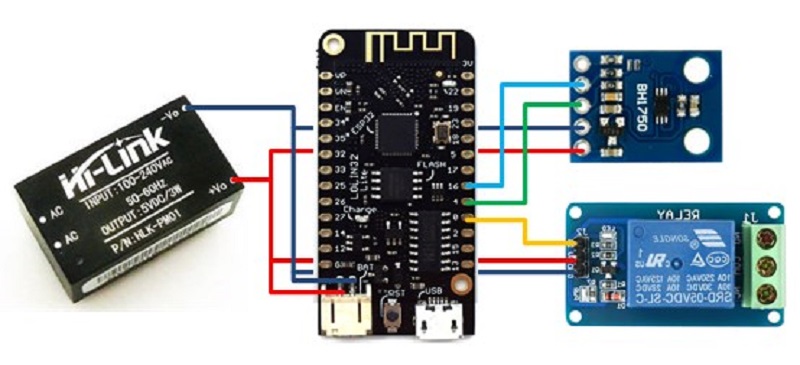
Now before you brush this off as simple n0Ob stuff – consider the following. He’s using a Lolin32 lite dev board, a BH1750 light intensity sensor and a relay to interface with mains for the lights. He wrote his own firmware and gets into the gritty details of developing the HTTP interface and flashing code to the correct memory.
We’ve seen a lot of ESP32 projects here at Hackaday, including this most interesting clock. Be sure to check out the video below to see the smart lights in action.


Nice project as a idea.
But you have to think of safety.
Never have open mains with extra low voltage.
You always have to think of safety..
Nice Project I will be looking at your code.
Let me rephrase this.
Never have open mains and extra low voltage in the same box, not separate properly.
That’s an absurd statement. By definition any time you are producing low voltage from mains, you have to have some point where they are in the same box. It’s utterly impractical to do otherwise. While I agree that the way this is laid out doesn’t provide safe separation, there are ways to do it. What I’ll usually do is have a relatively constrained area of the PCB with obvious wide traces that is the high voltage section leading up to the power supply module. This section will include any MOV, Fuse, Protection Resistor (I find putting 1Ω ceramic resistor of appropriate voltage on the hot side before the MOV works nicely to help current limit any load fed to the MOV without significantly impacting the downstream circuit. It does eat a small amount of power efficiency, but for anything that is mains powered, it’s not significant (at US$0.30/kwH it adds up to less than $0.05 per year in my experience, YMMV). Since the PCB is rigid and I mount everything else to other parts of the PCB with at least a 1/4″ (often quite a bit more) distance from any high voltage traces, I don’t see any safety implications beyond the ones you have with mains voltage in anything, even without the low voltage parts.
Esp32 seems like overkill for this, the venerable esp8266 would do it just as well.
That’s what I was thinking, but perhaps the person here went with the esp32 simply because they had some lying around and were familiar with it? The esp32 does consume more power, but it’s not an enormously large amount, so maybe it just doesn’t matter that much. Me, if I were going for something like this, I’d use one of the Nodemcu-style esp8266-boards I have about and remove the LEDs and the USB-TTL-chip from the board to bring its power-consumption down even more.
Or simply re flash iteads sonoff wifi IOT switches.
They use esp8266, have the power supply and relays all rolled into a tiny safe package for a few pounds. You can roll your own firmware directly or use something like tasmota with mqtt.
Safe… erm that’s what I thought – until a couple POW16s melted right through and just plain good fortune prevented a house fire from starting. Apparently some POW16 units were subject to a recall a while ago – the supply track is too thin and fails under moderate load – but the bad units are evidently still in the supply chain.
wow, wow, wow … ¿do yo have a link for that info?
I have some on those POW units and obviously don’t want to have my house in fire.
Google “itead recall”.
ITEAD have removed the recall notice from their website. Luckily archive.org has a copy
https://web.archive.org/web/20170321011207/https://www.itead.cc/blog/sonoff-th16-and-pow-recall-notice
TBH, not at all impressed by the “send a photo of your melted device to receive a refund or replacement”. This was a serious defect that could result in a fire FFS !
It’d be the equivalent of a car manufacturer saying “we’ve identified an issue with the brakes, please contact your dealer for remedial work once they’ve failed and you’ve hit a tree”
Thank you, just wanted to find an image to see if my switches are suceptible to starting a fire. I’ll have to open them and see.
I didn’t know about this, so thanks.
Reading the notice – the problem is with the PC tracks not being heavy enough to carry the full rated AC current, due to the factory not larding enough solder onto those tracks.
A few points:
– if you keep the loads modest, like just a few lights (eg < 500 W total), you won't likely have a problem
– if you've opened the device to reflash it, take a couple of extra minutes to solder some solid copper wire onto the AC tracks
Ideally, mains-carrying devices should be in a metal enclosure, but that would kind of mess up the Wifi part.
@Mr.Grumpy
Seems a lot more like a proof of ownership to my trusting mind…
@Ken the fault is not obvious when reflashing. I am guessing you are being your suggestions on the basic in line switch, you cannot fix the pow16 issues with solder. Also, most would purchase a pow16 with the objective of switching heavier loads. My failures were switching a resistive load at 10amps. No one in their right mind would deliberately distribute products flawed in such a fundamental way, but it is very clear itead could have done a much better job of spreading the word than they have done.
@eccentricelectron
Why can’t the POW16 be fixed with solder?
Wasn’t the failure cause the small amount of solder used on the power tracks?
Shouldn’t adding solder (or wire) fix them?
why would anyone use the esp8266 anymore since the esp32 is out and far superior.
¿Lower consumption?
Because the ESP8266 is still more than good enough for most things. And it does low-current sleep better than the ’32.
But mainly because I have a drawerful of ‘8266s to use up.
Cheaper, better supported, simpler, more compatible, higher power usage (for battery applications) etc. The tooling and ecosystem are not as developed as the ESP8266.
Not to mention the ESP8266 is still plenty powerful. Most people’s use cases are probably barely scratching the surface of what these can do. Hell there are still people using arduinos and connecting to the ESP8266’s serially with the stock firmware, when you could do everything the arduino is doing and more directly on the ESP8266 with no sweat if you flash the ESP8266 with the arduino IDE.
Hi all! Thanks for your comment! I agree that the same device could be based on other microcontrollers (esp8266, PIC…). On my website I’m publishing a tutorial about the esp32 chip and this project is somehow the “sum” of what I explained about that chip and the esp-idf so far (how to connect to a wifi network, how to get time from NTP server, how to publish a website, how to store/retrieve data from an SPIFFS partition…).
Since you went with the esp32, did you think about extending the functionality with bluetooth, too? I mean, the hardware is already there, just need the software for it.
Sure, bluetooth is the topic of the upcoming tutorials ;)
I like the project and I have similar projects in my house but I also have to offe my concerns about the safety aspect.
Please correct me if I’m wrong but it appears that there is a few uninsulated mains connections and the use of earth wire (green and yellow) for power wireing.
If anybody is building something mains powered please use the correct wireing and insulate every thing. You may be aware of what’s in the box but sometime after you’ve put your project aside and someone else picks it up your construction might not be immediately evident.