If you are a devotee of audiophile-quality analogue hi-fi, switching between sources simply can not be done through a solid-state device. Only physical switches will do because they come without the risk of extra noise or distortion that their silicon equivalents might bring.
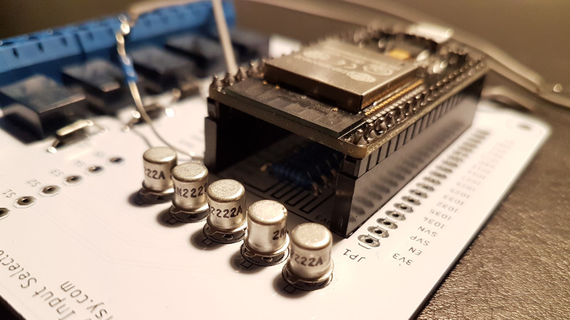
That is the philosophy that lies behind [Skrodahl]’s relay-based audio switching board, which boasts 5 high-quality relays each handling a stereo input, with their control passed either to a rotary switch or to an ESP32 module. The ground connections on audio and switching sides are isolated from each other to avoid transient noise finding its way to the speakers.
You might think that an audio switching board is a very simple device indeed and thus not worthy of Hackaday’s attention, but it’s surprisingly easy to make a mess of a module like this one and they have put in some effort to avoid the pitfalls. The metal-can version of the switching transistors seems a little overkill, but fancy audio is a funny business.
If the ESP isn’t your bag, we’ve brought you another relay based audio switcher in the past that used an Atmel chip.


Some swear by relay-switched stepped attenuators instead of pots, too. They click a bit when you’re changing the volume, though.
There are PGAs specifically designed for audio such as the PGA4311. And that brings up a big advantage of analog audio – that is it trivial to mix multiple sources. Doing the same in the digital domain is especially difficult if you have to account for the sources having slightly different clock frequencies or completely different sample rates.
sure, because human ear is more sensitive to distortions than low strength QAM256 signal mixed by pretty much same chips
I am quite sure “mixing digital signals” means the summing up of digital audio signals. I can not see much use in summing/mixing of QAM256 signals in the voltage domain. This would not generate a digital addition.
Why would anybody be mixing a QAM signal anyway? This is a digital transmission data encoding technique. A modem for example would decode this and produce a serial data stream which could be mixed (in the digital domain) but QAM and especially QAM256 would be a nightmare and a disaster to mix without decoding first.
BTW: mixing signals in the voltage (analogue) domain is never a digital signal mixer. Digital signals mix with mathematical addition of the individual digital samples (n bit numbers) and maybe scaling to avoid clipping. You can’t just use a couple of resistors to connect two digital audio streams and not expect an audio mess.
I hope those relay contacts are ion aligned and the magnetic flux from the energized relay coils is sufficiently isolated from the nearby wiring to prevent any chance of induced dc offset in the switching circuitry .
Even though they may be dc coils the static magnetic flux can impeded one half of the audio signal resulting in unbearable distortion.
I have developed a coating that can be sprayed on the circuit board tracks which neutralizes air/copper ionic interaction to smooth the laminar flow in the surface of the copper.
One of my friends has some “magic field” around her that improves the sound quality of any analog audio gadget she handles. (At least if the gadget was half decent to begin with…) I confirmed the effect with some family members who do not know her so that confirms it wasn’t a mental bias. The irony? She’s a software engineer.
It doesn’t matter if they know her, you need a proper A/B/X test.
How do you mean “handle”? You mean she messes with onboard trimmers and stuff? Or just picks it up?
You sell snake oil!? Do you have anything that can help with the intolerable distortion of misaligned electron flow? And maybe the electron scattering at junctions, solder joints and bends in the copper pcb traces? I cannot believe that anybody could post with a straight face the utter rubbish you have posted.
A static magnetic field can have no appreciable impact on the signal passing through the relay, electrons do not have a ‘laminar’ flow, ion aligned relay contacts is utterly nonsensical and static magnetic fields induce nothing and especially not a ‘dc offset’. Only a time variant magnetic field can induce a current in a conductor. So unless the magnetic field is changing or the conductor is moving through the magnetic field such that the magnetic flux density experienced by the conductor is changing with that movement there is no induced current by the magnetic field in near by conductors.
Nobody is advanced with misinformation.
Whoosh.
Damn! And i was just about to buy a tin of that stuff too…
You must be fun at parties….
Believe it or not, I really am! :-)
Until somebody starts spouting peudo science as being credible science or just a load of rubbish being put out there as a solid fact. When they bury it under technical words and make it sound all very complicated so people don’t ask questions and some even believe it then I take it as my duty to science to tear them a new one.
I’ve wasted too much of my career arguing with the myth and legend other engineers believe to have any tolerance of it. Makes me a bit of a troll I guess but I hope I reduce the misinformation at the same time. One less myth or legend is a good thing. Sorry if I was a bit heavy handed. It was a very provocative bit of…. crap! And I had to destroy it. ;-)
“…anybody could post with a straight face…” ? I am quite sure this was not the intention or the case. :-) Audiophools deserve to be ridiculed.
Is this an April Fools joke? It surely reads like one. This is pure esoteric audiophool nonsense that belongs in the audiophools bumkin-bin.
Now, if it only was made on a silver pcb instead of copper…
jokes aside, I’ve always hated solid state switching, every device I’ve used with it leaks some audio from other inputs.
Those must be some shitty solid state switches. But when you can do it with a relay, why not. Reed relays can be completely silent too.
It can be done with good off-state attenuation. One possibility is a T structure: 2 series switches for “on” and a shunt switch for “off”. The use of the right signal impedance levels is also important and probably distribution on different chips. A relay has also some capacitance, so you do not get infinite attenuation.
Mechanical switch contacts, that is switches and relays will not introduce the distortion that semiconductor switches can, but depending on the contacts they can cause all kinds of hissing and popping. How many old stereos with selector switches have you had to crank back and forth a couple of times when changing inputs before you finally broke down and took the thing apart to clean the switch. And at some point cleaning the switch is not going to do it.
And to the person who said they always hear leakage from solid state switching, I am impressed and near 100% of my audio devices now use solid state switching and I can not hear any crosstalk at all. And at least on of the two devices that use mechanical switching, you guessed it, needs to have the switch cleaned….
I am known to wire a pair of inputs (the least worn jacks) direct to the input leaving no switches in the path to keep a good amp going in this age of single source audio. KISS.
Actually the problem within soldid state switching is the very small dimensions of the integrated circuit (a classic 74HC4052 for example).
You can make solid state switches out of discrete FET, so the channels are much more distant, and the noise between them will be much lower.
Mechanical switches or relays add up conductor length which will catch ambient EMI.
I remember a Tanberg high-end HiFi tuner-amp which used simple pairs of 1N4148 diodes to switch between sources, adding a polarizing voltage from the commutation switches to the selected signal.
Neat, simple, reliable, noise-free, no audio signal across switches, etc.
Sorry, I mean Tandberg, model TR-2075, year 1975. Still available on eBay at 650$
Normally I consider audiophiles to be overenthusiastic idiots. This is not one of those times. Totally agree physical switching is way less susceptible to noise.
And yet everything from video devices to scopes to RF devices have signal switching with frequencies into the megahertz range without introducing distortion or noise, but somehow signals in the sub-20-khz range are impossible voodoo magic that EEs haven’t been able to figure out. Right.
Or the people selling old relay-based equipment, who didn’t want to rework their designs, sold everyone else on a lie in order to keep selling their old crap.
So glad to see that the rational thinkers outnumber believers in woo. Audiophiles don’t listen to music. They listen to equipment, and fancy themselves to have elite abilities of perception that most modern labs can’t measure. Delusional suckers, the lot of them.
I know I’m necroing this but you guys keep comparing very tiny voltage/high bandwidth signals to low frequency audible signals and the two aren’t even remotely the same. Audio is an extremely complex waveform, often having massive slew rates that go from -4 to +4V faster than a typical RF signal can ever go, just from a simple symbol/crash during a heavy bass note. To reproduce all that constant variance accurately requires high bandwidth too just like your fancy RF devices.
Modulation of RF and data is very repetitive and predictable, mostly are simple waveforms like modulated FM radio, yet people still confuse the two. It is why audio devices perform significantly better and have an open airy soundstage the more bandwidth your preamp/output devices are capable of. You need about 60mhz bandwidth at least to reproduce complex audio waveforms or you end up with all kinds of ringing and delays in the rise/fall times which translates directly into distortion that ignorant people won’t even notice and always expected was there all along, yeah it makes that airy the soundstage disappear, the ones you guys constantly claim never exists! Anyone who says otherwise is looking at their P.eng too much and being ignorant of the facts.
Yes, delusional, why don’t you build your own system then and figure it out like the majority of us people do that understand what exactly is going on here. We don’t pay $100,000 on expensive audio crap because money is no object, we DIY our own significantly cheaper equipment that makes anything consumer look trash, but when consumer is all everyone is buying, how can they have a true opinion on audio? So yes, EE’s have indeed already figured this all out already, decades ago in Japan.
necroing necro but: this is completely wrong.
the nyquist theorem has a proof, there are conclusive measurements on the range of human hearing. the bandwidth needed is strictly up to 20kHz.
you could draw a waveform that ‘needed 60mHz of bandwidth’ but only if your output samplerate was 120mHz. this is a mathematical fact.
assuming you did have signal with 60mHz bandwidth going through a chain of equipment (preamp, amp, speakers) – at every nonlinearity it encounters the unnecessary part of the signal is introducing more IM distortion – non-harmonic, unpleasant. it would sound better filtered at source to audible range.
in studios people work at higher sample rates because it gives a bit of headroom for anti-aliasing filters on any digital processing that may introduce higher harmonics, puts the phase distortions of this out of audible range, lets noise shaping dither all live outside audible range. etc.
Until you test in the modern lab yourself, input some complex signal into an amplifier and look at what comes out, any consumer gear will be laughable on the output. Any capacitance on the cables will affect the output even, not sure what labs you guys use. Signals can still be very simple to reproduce and still modulate tons of data well into the ghz range… not sure how that plays a role however.
Actually, relays are notoriously bad and unreliable for low current applications such as audio input switching. Bad even for analog video. I have a high end Bosche Ferhinseh (sp?) Commercial Video monitor that Bosche had to junk entire product line because of intermittants in all the (Bosche) relays used for input switching. I got mine to work reliably by hard soldering signal input past relays.
Relays are fine for higher current applications, but get noisy and intermittant when used with low level signals. My choice for audio input switching would be either physical switches or Harris solid state switches.
Relays were fine for low-current applications until people started whining about mercury-wetted contacts.
Good thing you can still buy them from mouser then. I love how people make things worse to remove toxic chemicals, causing people to use more toxic chemicals to replace them, or completely work around the attempts to remove them, like special ordering 60/40 or mercury switches, or buying in stuff from countries that don’t care about those rules.
I once repaired an old magnetizer by shaking the thyratron tube (which had a portion of liquid mercury inside it). There was bad sputtering inside the glass, and it was triggering far too early. Shaking the mercury around “picked up” all the sputtered metal and rewetted the anode, cathode, and grid.
I buy 63/37 solder, I stockpile certain old components, and I utterly revile the lead restrictions of RoHS. Most lead is either A: part of the highly recycled lead-acid battery industry, or B: has been eliminated via the elimination of the MASSIVE quantities of leaded glass that was used in CRTs. While I can’t vouch for accuracy… I once read that solder accounts for only 2% of lead in the electronics industry, when including CRTs and Lead acid batteries.
If that is remotely true (I don’t know), then how much lead did we introduce by pushing for the mass discarding of those old devices, and replacement with modern devices that are MORE PRONE to failure than their leaded counterparts? I’d pay a premium if I could get certain modern electronics made with leaded solder! I really would! Lower manufacturing temps, less resulting mechanical strain on parts, as they cool from lower soldering temps than their lead free counterparts, significantly reduced or eliminated chance of tin whiskers or tin pest, more ductile solder joints… the list goes on.
RoHS was a knee-jerk reaction by legislators with no concept or clue as to how the electronics industry actually works, or what makes for a reliable product. It MAKES e-waste!
Go to bed, grandpa. And take your damn meds.
This is a highly unsuitable comment!
There is a reason, that leaded solder is still allowed for things like aviation or defense, where reliability is crucial. People always whine about “planned obsolescence” where it is not applicable, but accept lead free solder? this is the real way to reduce product lifetime. I don’t eat solder, so I happily use 60/40 (or 63/37) and would not buy anything else for electronics.
Opinionated.
And wrong. So very, very wrong.
Why is it so hard for people to try to learn about things before writing a lot of bullshit?
Do you even realize that leaded solder isn’t suitable to many types of uses? That modern electronic require different types of solder in a single product for it to work reliable (or at all)? That leaded solder isn’t suitable for low temperature solders as they often get a too low melting point? That tin whiskers isn’t a significant problem in modern electronics?
No. You don’t realize shit but are too stupid to realize even that. Fuck off.
@Megol said: “Do you even realize that leaded solder isn’t suitable to many types of uses?”
Such as?
“leaded solder isn’t suitable for low temperature solders as they often get a too low melting point”
That’s a manufacturing problem. RoHS solders tend to be higher temp than PbSn, which also cause other problems in manufacturing. RoHS is LESS reliable in higher temp and vibration applications, which is why aerospace electronics are excluded from RoHS regs.
“modern electronic require different types of solder”
REQUIRE??? RoHS solder is ‘required’ because of legislation, not technical need. Multiple chemistries are a response to other shortcomings of RoHS solder.
“tin whiskers isn’t a significant problem in modern electronics”
BULLSHIT! It was barely a problem worth mentioning before RoHS. Now it’s an epidemic. TIn whiskers were identified as the problem in several cases of Toyota’s sudden unintended acceleration problem, and they’ve caused at least one recall of pacemakers. Could you imagine having to endure an unnecessary surgery because some bureaucrat though the .5% of ALL the lead used in the electronics industry was a problem?
I suggest you come to grips that you don’t know as much as you *think* you do, and read this:
https://nepp.nasa.gov/whisker/reference/tech_papers/2011-kostic-pb-free.pdf
The fact is, RoHS solder has caused a significant increase in failures because of tin whiskers. That RoHS solder sucks. Full stop.
@ richfiles said: “I once read that solder accounts for only 2% of lead in the electronics industry, when including CRTs and Lead acid batteries.”
Not quite. Solder accounts for .5% of lead in the electronics industry. Batteries 88.3%. The remainder is used elsewhere.
Pretty much everything else you said is backed up by this paper I found at NASA.
https://nepp.nasa.gov/whisker/reference/tech_papers/2011-kostic-pb-free.pdf
At last somebody nailed it. The perfect mechanical switch for the application is a mercury wetted reed relay. At some point in the life of the equipment you might have to give the thing a shake and a tap in a particular direction because the mercury gets a bit stubborn and the reed doesn’t open like it did when new but in the mean time, a clean, reliable and low impedance switch that will probably cost a small fortune. High end production test equipment used to use huge banks of them.
There are other options as well though: Teledyne make some high spec relays without mercury but otherwise intended for the same high end production test gear. They are hermetically sealed in steel cans (shielded in other words) but still have a minimum load of 10 to 50uA and 10 to 50mV and tend to be pretty expensive. I can’t remember the model I used but I do remember a $43 price tag per relay.
For audio work they probably still won’t cut it: isolation (open contacts) is around 70dB in the audio range using 50 Ohm source and load impedance. At the typical load resistance of audio gear being in the 10’s of kOhms this figure of 70dB could be a good deal less and even if it isn’t it probably won’t provide the isolation required without a shunt on the un-selected inputs ( the T section idea Martin mentioned earlier).
I still like wetted reed relays or solid state switches done right. Commutating diodes (Jibe) are a far less appealing idea unless the non linearity and even order harmonic distortion of the diodes won’t bother you.
I’d never thought about using relays…that’s a great hack, cause you don’t have a lot of loss there.
I was thinking of using JFETs to do the same, but you could introduce some distorsion if the circuit is nol designed correctly
So why not design it correctly? If you consider the power needed for the coil, then there are quite some losses.
What about the CMOS 4066 Bilateral Switch for Audio or Video???
They are quite good, in the right circuit used correctly).
The row of cans looks neat, but if one is worried about magnetic fields, shouldn’t de metal can transistors be much closer to the relays that they drive?
Actual 2N222222’s as well! Practically the original transistor!
The reason why audiophiles love relays for switching is because they can guess at the source during ABX testing from the sound of the clicks.
Use socketed relais to enable swapping, so the audiophiles can have a go at finding the best sounding relais :P
You could get past that by buzzing the relays. Have them all switch at some high rate, then finally settle on whichever setting you want. If they’re clicking / buzzing too fast to follow, you couldn’t keep track.
I suppose you probably shouldn’t, but relays are tough and rated for loads of contact changes, should be fine for the amount of times a switching box gets used.
In a few years you may start to notice that the audio signal is either appreciably deteriorated or not present at all and at that point have a look at the minimum switching voltage and current for the relays you are using. All dry contact relays have a minimum voltage and current switching rating because they need something to keep the contacts clean. Possible exception would be reed relays but even then for high end data acquisition systems a wet reed relay was the more common choice but I’m not sure they are still available (the wetting agent was mercury). A dry reed relay should be ok for many years if the hermetic seal remains intact. The 10uA/10mV minimum switching spec for the TQ2 relays is not to be assumed sufficient for keeping the contacts clean enough for your purpose. They are telecom relays and as such expect to be switching a lot more than 10mV or 10uA.
I do agree that relay switching is the way to go. It makes avoiding ground loops easy and if you use the N/C contacts properly or use more relays you can get cross talk and isolation (source to source) down to crazy small numbers. You just need a relay that can do that this year as well as next… and the next after that.
I’m convinced all these audiophile “rules” are just made up by people with financial interest in the old stuff.
Relay switches for audio signals? Those better be solid gold contacts, not cheap gold plating, and cooled to within 2 degrees of absolute zero for superconduction. Otherwise I can hear the difference, if the contacts warm up past 10 kelvins it sounds like crap and anyone who doesn’t disagree must be deaf.
/sarcasm.
Hah, that’s exactly what I am going to build! Also going to add a Lightspeed Attenuator (optical volume control with LED and LDR), driven by the ESP. And possibly use the ESP as an Internet radio.
Both Eagle project files and gerbers for this project is open source, no strings attached. There’s also an Eagle library file for this particular ESP module available on the project page.
Small stepper motor driving a positioning wheel (or rod whatever) combined with reed switches should be a close to perfect solution for low voltages: the mechanism can be expanded to almost any number of contacts and only draws power when changing source. Is that perhaps already available?
Transistor driven reed relays…. Work great for my Cimron 6200 DVM. Enjoyable to listen to as the transistor driven reed relay switched Kelvin-Varley ladders solve for null….