It’s easy to dismiss decades old electronics as effectively e-waste. With the rapid advancements and plummeting prices of modern technology, most old hardware is little more than a historical curiosity at this point. For example, why would anyone purchase something as esoteric as 1980-era video production equipment in 2018? A cheap burner phone could take better images, and if you’re looking to get video in your projects you’d be better off getting a webcam or a Raspberry Pi camera module.
 But occasionally the old ways of doing things offer possibilities that modern methods don’t. This fascinating white paper from [David Prutchi] describes in intricate detail how a 1982 JVC KY-1900 professional video camera purchased for $50 on eBay was turned into a polarimetric imager. The end result isn’t perfect, but considering such a device would normally carry a ~$20,000 price tag, it’s good enough that anyone looking to explore the concept of polarized video should probably get ready to open eBay in a new tab.
Likely many readers are not familiar with polarimetric imagers, it’s not exactly the kind of thing they carry at Best Buy. Put simply, it’s a device that allows the user to visualize the polarization of light in a given scene. [David] is interested in the technology as, among other things, it can be used to detect man-made materials against a natural backdrop; offering a potential method for detecting mines and other hidden explosives. He presented a fascinating talk on the subject at the 2015 Hackaday SuperConference, and DOLpi, his attempt at building a low-cost polarimetric imager with the Raspberry Pi, got him a fifth place win in that year’s Hackaday Prize.
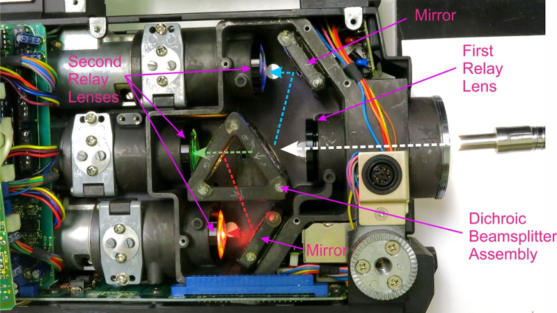
While he got good results with his Raspberry Pi solution, it took several seconds to generate a single frame of the image. To be practical, it needed to be much faster. [David] found his solution in an unlikely place, the design of 1980’s portable video cameras. These cameras made use of a dichroic beamsplitter to separate incoming light into red, blue, and green images; and in turn, each color image was fed into a dedicated sensor by way of mirrors. By replacing the beamsplitter assembly with a new 3D printed version that integrates polarization filters, each sensor now receives an image that corresponds to 0, 45, and 90 degrees polarization.
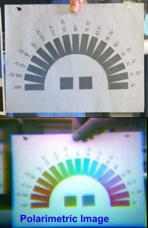
With the modification complete, the camera now generates real-time video that shows the angle of polarization as false color. [David] notes that the color reproduction and resolution is quite poor due to the nature of 30+ year old video technology, but that overall it’s a fair trade-off for running at 30 frames per second.
In another recent project, [David] found a way to hack optics onto a consumer-level thermal imaging camera. It’s becoming abundantly clear that he’s not a big fan of leaving hardware in an unmodified state.


NTSC remains a 60Hz standard, not a 30Hz standard. It encodes a ≈440×480 image (typically visible: ≈400×450) every 1/60th of a second, and throws away half the vertical resolution prior to transmission. Modern video capture equipment that throws away half of this data, or simply “weave”s two fields together ignoring that they’re of two different times separated 1/60th of a second apart, is doing everyone a disservice.
Now, pedantry done, this is pretty darn cool.
please read up on interlaced video and why is was developed before posting comments here. you look silly
Knowing more about interlaced video than you is exactly why I commented.
In older video tube based devices like this one, every scanline is from a different moment in time; approximately 1/16000th of a second later. There’s no frame store. Interlacing happens at the moment that the electrons are pulled off the sensor. Every 1/60th of a second, entirely different lines are pulled off from 1/60th of a second before.
Claiming that this is a 30fps video source is simply and unequivocally wrong. There are new images every 16ms; they differ from the one 16ms before by being of a subtly different vertical offset.
Claming there is a full image every 16.ms is wrong it is only halve a image NTSC has 29,97 frames a second or 59,94 fields a second, 30 and 60 is only with black and white.
Ah dang it! A few years ago i found 2-3 cameras in the university’s trash container for electronics, at least one of them worked (i didn’t test the others) and they all looked very similar in design / age…
Threw them back in the trash because of limited space and not knowing what to use them for. :-/
Mines? Well that’s come in handy for the upcoming apocalypse.
I wonder if it wouldn’t have made sense to “turn that project upside down”: If the important bit is the polarization filters and the mirror setup, why not replace the sensors by cheap smartphones or, if you want to do the work, your own set of digitizers to gain better resolution / fps rates? Just keep the optics and redo the electronics sounds like a more promising approach than keeping everything “because it’s there” …
So… if it’s sufficient to have three polarization filters on a beam-splitter from the main lens, couldn’t you also adapt a modern HD 3-sensor camera in the same way? I mean, it’s a lot more expensive than an obsolete used vidicon SD cameras, but if you’re talking life-critical “real” applications, it might be worth it just to have something that can be bought “in quantity.”
It seems that (current) three-sensor HD cameras start at under $2500, with used older 3-sensor cameras at about 1/10th that.
For that matter, it doesn’t seem too impossible to either implement your own beam-splitter path in front of some cheap cellphone modules, or retrofit something like this “found” camera with modern sensors…
(never mind. Reading more carefully, I see you tried that.) I was wondering if one of those tiny cameras would just be impossible to retrofit :-( )
An array of cheap webcams later and you’ve got a high resolution version. A little minor surgery and you’ll have some limited infrared too. Perhaps go with nine or even sixteen cameras if you can stretch to processing the images fast enough. Shame there’s no easy way to etch off the colour masks on webcams so with a software tweek they would see really triple [quadruple] resolution black and white. 12MP now becomes 36/48.
Crazy math to interlace pixels for the whole image verses interlacing images for each colour. Decisions, decisions.
Apparently not so hard…
https://petapixel.com/2013/08/04/scratching-the-color-filter-array-layer-off-a-dslr-sensor-for-sharper-bw-photos/
Apparently that’s been done too. Maybe might stumble on something awesome nobody has tired eventually.
https://m.youtube.com/watch?v=RpXNyWPfs8E
While I had originally had the same thought, upon further inspection, it would be very difficult to do this project that way. You couldn’t use the webcams as is; you would have to remove the lenses and then do the delicate work of removing the filters from the sensor itself.
Assuming there is no special requirements for the digital sensors compared to the old analog sensors, it would be taking some extremely close up shots since they are much smaller than the original versions. This makes it even more complicated since any defects in the optics will be magnified.
I actually think that the DOLPi-MECH version of the project is the superior version in spite of how slow it is. It could be improved by switching the servo-based mechanism to something similar to a DLP color wheel with variable speed control to allow it to take photos as fast as possible.
Perhaps more exciting would be a mix of the two methods; use three complete camera modules, take the photos simultaneously, and stitch them together like modern smartphones do. It still wont’ be completely accurate, but it should be close enough.
I think parallax problems may be annoying when using three separate cameras. Maybe one camera with a quickly rotating polarization filter in front of it? Likely requires a global shutter sensor for good results. There are old global shutter machine vision BW (color also, but more rare) cameras on ebay quite cheaply. These usually also have a frame strobe input or output for synchronizing a strobe or the wheel in this case.