When you’re debugging two bits of electronics talking SPI to each other, there’s a lot that can go sideways. Starting from the ground up, the signals can be wrong: data not synced with clocks right, or phase inverted. On top of that, the actual data sent needs to make sense to the receiving device. Are you sending the right commands?
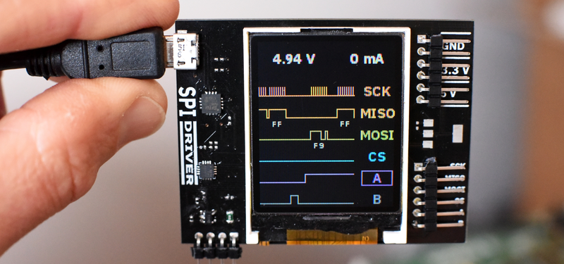
When nothing’s working, you’re fighting simultaneously on these two fronts and you might need different tools to debug each. An oscilloscope works great at the physical layer, while something like a Bus Pirate or fancier logic analyzer works better at the data layer because it can do parsing for you. [James Bowman]’s SPIDriver looks to us like a Bus Pirate with a screen — giving you a fighting chance on both fronts.
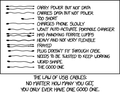 SPIDriver also has a couple more tricks up its sleeve: a voltage and current monitor for the device under test, so you don’t even have to break out your multimeter when you’re experiencing random resets. We asked [James] if these additions had a sad history behind them. He included this XKCD.
Everything about SPIDriver is open, so you can check out the hardware design, browse the code, and modify any and all of it to your taste. And speaking of open, [James] is also the man behind the Gameduino and an amazing FPGA Forth soft-CPU.
It’s fully crowd-funded, but it closes in a couple of days so if you want one, get on it soon.
And if you want to learn more about SPI debugging, we’ve written up a crash-course. With the gear and the know-how, you at least stand a fighting chance.


one thing i always wanted in the lab is a pocket protocol decoder
lots of SPI, I2C and UART in designs and constantly busting out the logic analyzer and firing up a laptop to see what’s up can be a bit of a chore
very nice project
I’m always vaugely annoyed at the lack of features in common multimeters. 1MSPS scopes aren’t all that hard, and are super handy. Imagine if meters could receive UART? Even at 9600 baud, it would be enough for the device to provide debugging info.
There’s no all in one super tricorder type devices out there that do what Android phones did for cameras, PDAs, MP3 players, and GPSes.
This is a really cool project. I’d love to see more test gear move in this direction.
I smell a kickstarter coming on…
Not all what you asked for, but I just stumbled on this and it sounds interesting
https://www.crowdsupply.com/espotek/labrador
I made one to monitor UART on a screen http://www.electrobob.com/ser-show/ . My plan was to extend it to I2C as well, but that would have been more work since you can’t just use the HW I2C. In the end I relied on I2C decoder from my other ready made tools.
The reason SPI is easy is because you can still use the HW module (you will need 2).
The MiniDSO/TS100/ES120 people are making a mini battery powered 4 channel logic analyser with SPI/I2C/UART decoding in the same style case as the MiniDSO units. Search for LA104 and you’ll find it. They’ve released (partial?) source for the MiniDSO units so I expect the same for this LA104 but you’ll have to wait for it to be launched to confirm.
Input
Channels: 4
Max Sample Rate: 100Mhz
Minimum capture pulse width: 10ns
Input impedance: 1MΩ
Output
Channels: 4
Mode: SPI, I2C, PWM
3V output Channel: 1
Storage: 8MB USB flash disk memory
Screen Size: 2.8”
Screen Resolution: 320×240
Battery: 500mAh
Dimension: 100mmx56mmx8.6mm
Weight: 83g
I like this project too, great foundation for a universal serial protocol interpreter, thanks :-)
The day is ruined, nothing will get done, please don’t use xkcd links in articles. :(
Would you rather someone linked you to the XKCD page on TV Tropes?
My work here is done!
I would love something like this, but for I²C, sitting as a man-in-the-middle, so that I can know which of the devices is pulling down that line.
This. A device like that should definitely be able to decode I2C, and perhaps other protocols that are common with microcontrollers.
This device seems to be more aimed at debugging during the initial prototyping phase rather than the “what’s wrong with this existing device” phase. So it’s your computer SPI gizmo.
But I really like your idea of an I2C man-in-the-middler to track down a bus-hog. What would you do, insert a small resistor and measure voltage on either side of it? You’d have to be careful about which side the pullup resistors are located on, etc. Hmmm….
I am pretty sure that in the depth of the Linear catalog you’ll find a chip that allows just that
depending on the power consumption of your slave you might be able to measure the ground current of it and figure out if it is forcing the zero level or not.
Spid River? Never heard of it?
As long as the price is right I would be game. Definitely cool on the portability factor :)