Oh, there was a time when you could prototype just about everything on a breadboard. The CPU in your computer came in a DIP package, and there were no BGA packages. to be found anywhere. In the forty years since then, chips have gotten smaller, packages have gotten more cramped, and you can barely hand-solder the coolest chips anymore. No worries — companies are still spitting out dev boards with 0.1″ headers, but there’s a problem: they don’t fit on a solderless breadboard. They’re too wide. Our world is falling apart.
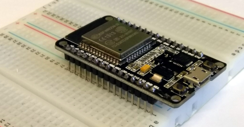
[Luc] had a problem when he was playing with a few NodeMCU dev boards. These are too wide for a breadboard. [Luc] came up with not just one solution, but two. This is how you prototype with dev boards that are too large.
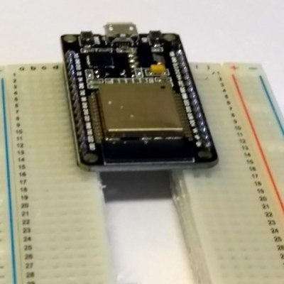 The solution came to [Luc] when he realized the center of every breadboard has no electrical connections, and was simply held together by a little piece of plastic. Yes, he took a hacksaw to the breadboard. This is technically a hack.
With two halves of a solderless breadboard torn asunder, [Luc] had an easy way to prototype with dev boards that are just too wide. But there is a simpler solution [Luc] realized after he destroyed a breadboard: those ubiquitous solderless breadboards have detachable power rails. If you simply take one of those power rails off, you have an easy way to use two breadboards across a module that’s too wide for one solderless breadboard.
Is this a hack? Oh, absolutely. [Luc] used a hacksaw. It’s also a nice reminder of a common trick that the noobies might not know. Thanks for that, [Luc].


Suggestion: One general RSS and second one, actually worth reading time? [Y/N]
And Benchoff strikes again.
https://www.youtube.com/watch?v=P-Eqx3OETuw
This is the proper time to use the word “literally”. This is literally a hack.
Yep. Been there, done that: https://youtu.be/TKYMAqLvCpg :-)
Yawn!
that is literally a hack.
my ideal bread board would be in the form of lego bricks where you can arrange smaller sections of connectors however you want.
That’s a great idea :D
If the spacing of the LEGO nubs works out with the 2.54mm spacing of DIP pins you could even make them lego compatible… I think I have to get my calipers out and start modeling :)
1 lego unit = 8mm.
100 lego units = 800mm = 254 pin sockets
unfortunately you can only reduce that down to
50 lego units = 400mm = 127 pin sockets
and 127 is a prime so it would seem that things are dead in the water.
unless move to a different pin type (say 2mm, so one lu can support a 4 wire bus) and just use dip adapter bricks to tie into it. even go as far as bricks with pogo pins that can accept various surface mount parts without having to use an adapter board (meaning you can later use the same parts on a pcb after you got through the prototype phase). this also lets you condense the size of the prototype a lot and allow for higher frequency signals.
you might also be able to ignore misalignment all together since you can just stick a bus bar (say 3 wire bus per lu) wherever you want, so you end up with most of your jumper wires being of the short variety to transfer signals between bricks. large bricks, say 4×6 lu can be used as for the cross matrix parts. and support 12×18 rows of pin sockets allowing for the classic 5dip5 layout that can support a 36 pin dip chip.
Your calculations are off. 800mm doesn’t give 254 pin sockets, but ~315 (800mm / 2.54mm/pin = 314.96pins).
Now, the LEGO standard for this is 1 pin per LU, as in the El.plate 2 x 8:
https://www.brickowl.com/catalog/lego-white-electric-plate-2-x-8-with-contacts-4758
I remember being so impressed that it would correctly route the power even when you attached one of these at 90 degrees to another one. :)
I wonder if the CEO of K’nex heavily googles for phrases that mention their product the way we use Lego to describe things.
Closest I could find Mini Solderless Breadboards Prototype Protoboard 25Holes UNO DIY Kit Universal Bread Board 25Tie-points Boards With Base
http://s.aliexpress.com/Vj6b2m6V?fromSns=Copy to Clipboard
Hmm, some years ago I just got another white plug board (with or without the side fixed bussing) positioned at the correct spacing so no cutting needed, though back then the white plug boards were a bit more expensive. Was there a space constraint preventing that perhaps or time issue getting another – nm – rhetorical question – each to his own…
A quiet literal Hack: Benchoff needs to be drawn in a Roadrunner and Wile Coyote cartoon
Does this really deserve to be posted as a “hack” ?
Purely for the wordplay
The ones I have come apart like that. Who’d a thought?
Personally, I just use the solution in the main pic, so I can have both 3.3v & 5v rails right in the middle with my NodeMCU. Even just using a single power strip, I can still put two jumpers on any pin.
For my Nano, I first placed the headers beside the board, then soldered an ‘L’-shaped piece of stiff wire from the header into each hole. It made for a *very* mechanically sturdy joint. https://photos.app.goo.gl/mk3xncEQhTZmAu2H8
Same here. Works great.
Does anybody NOT know, that there are also smaller ESP8266/32 boards, that actually DO fit on standard solderless breadboards?
Last weekend, I fired up a NodeMCU clone, and it fit OK on a standard breadboard, though it only left exposed one free hole per module pin.
This is literal breadboard hack
https://www.youtube.com/watch?v=HrG98HJ3Z6w
I did something like this for a wide dev board holding an NXP LPC2119 (ARM microcontroller):
https://www.flickr.com/photos/anachrocomputer/6647102295
and the result:
https://www.flickr.com/photos/anachrocomputer/6909756097
+1
I probably would have forgotten to protect the sockets with tape before sawing…
I did something like this a while ago for NARROW stuff: Ribbon and other dual-row connectors straight into breadboard without having to “span the trench”:
https://farm6.staticflickr.com/5528/11377373075_3bb6b5087c_z_d.jpg
https://farm4.staticflickr.com/3784/11377383293_fc8ff19998_z_d.jpg
John Honniball says: “I did something like this for a wide dev board holding an NXP LPC2119 (ARM microcontroller)”
Not a hack. You didn’t use a hack saw.
Why not use two breadboards instead???
Just what I wrote though different wording, then you have only one pin occupied each side so more pins available than other methods, so I’m curious if the choice to cut is due to space or some other constraint not articulated ?
Is it mounting perhaps though plug-board bases have self adhesive
Was looking for this reply =P
if all your breadboards have power bus lines on the edges, then there can be a size of board too wide for one breadboard but not wide enough to span two power buses…depends on the specific geometry.
I chop up breadboards all the time to fit my projects. Regarding this statement: “These are too wide for a breadboard.” An arduino is even wider. So instead of fitting the arduino onto a breadboard, just stick a sawed off bit of breadboard between the headers using double stick foam tape. (This works best with the arduinos that have the surface mount atmega.)
“those ubiquitous solderless breadboards have detachable power rails.”
some of “those ubiquitous solderless breadboards have detachable power rails”
FTFY
Most of the time, when people write or say “literally” they should write or say “actually,” actually.
So they should literally write actually? Oh wait we’re typing, that doesn’t work.
So many words for a pun. But it’s OK.
I don’t see what the problem is…
I just cut out the middle of the devboard to fit the bread board.
For some reason none of my projects ever work. ;P
wow! i love it. my mind keeps rebelling at the idea of sacrificing one of my breadboards, but i definitely love it!
They should be so cheap it doesn’t matter.
Doesn’t anyone buy the breadboards with the removable power rails anymore? This is one of the reasons they sell them. You can even get them from Microcenter.
Last cheep board I got was around $4, even I think I could afford to buy two of them and straddle the sides. It would be handy to have the power bussed down the center as well as the outsides. I don’t think I will be cutting mine in half any time soon.
What the hell happened to the 600mil breadboards from the 80’s? You used to be able to get them for 40 pin DIPs. They’d be perfect for most of the Teensy style boards.
Just glue 2 perf boards together and still let your self use standard DIP packages
Thanks, Brian.
I was inspired by the article and the amusingly correct use of the word ‘literal’, but too lazy to go to the garage and get my hacksaw, so I printed this (joins two breadboards) on Thingiverse (Thing 3072683):
https://www.thingiverse.com/thing:3072683
https://cdn.thingiverse.com/renders/d8/c4/b8/7b/42/1dd25abd5ca19a3eae4790c5350cca9c_preview_featured.jpg
Not sure how to link or add a jpg in a comment, so here goes (might fail miserably) …
Not a hack! (-saw requiring solution.)
You realize, of course, I saw that coming…
Absolutely fabulous. Saved me.
7 years later and nobody is selling wider breadboards. Sad!