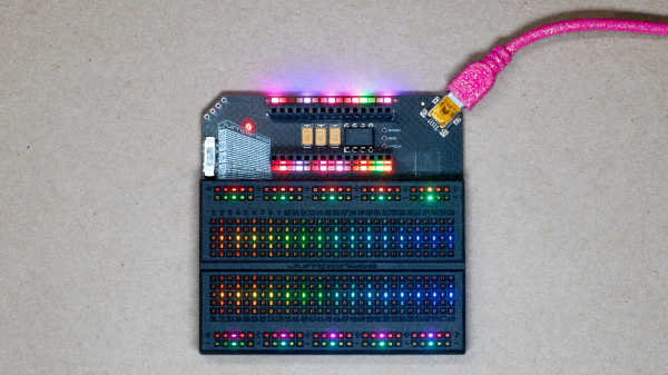
Jumperless is a jumperless breadboard with multicolored LED visualization of signals in real-time. Sounds like magic? This beautifully executed entry to the 2023 Hackaday Prize by [Kevin Santo Cappuccio] uses a boatload of CH446Q analog switch ICs to perform the interconnect between the Raspberry Pi Pico header and the jumper board (or breadboard if you prefer.)
This will add some significant resistance, but for low currents and digital logic levels, this should not be a major concern. Additionally, there are two DAC channels and four ADC channels to help break out of the digital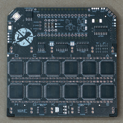 world, which could make for some very interesting non-trivial applications.
The visualization of the Pico header signals is solved neatly with a tiny wishbone-shaped PCB that is reverse-mounted to the back of the main board to illuminate upwards. The masking of the labels is done by using copper to mask off the individual signals and solder mask to draw in the legends. This PCB-level hacking is simply wonderful to see. The PCBs are designed with KiCAD, the design files for which you can find here. It appears however that [Kevin] needed to have the spring clips for the jumper board custom-made, so you’d need to contact them if you needed to get some for a build.
On the software side of things, [Kevin] currently recommends using Wokwi, to run the Arduino stack applications and to perform the signal routing to the virtual jumper board. You can follow how it works internally here. A Python-based bridge application runs on the host computer, which takes care of programming the interconnects as they are constructed, which looking at the demo in the embedded video, appears to ‘just work.’
One word of caution though — the bridge app uses Python requests and Beautiful Soup to scrape the Wowki project page, which could potentially make it vulnerable to getting out-of-sync with updates, so hopefully [Kevin] will keep track of this and keep them in sync.
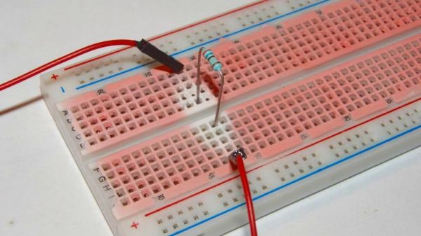
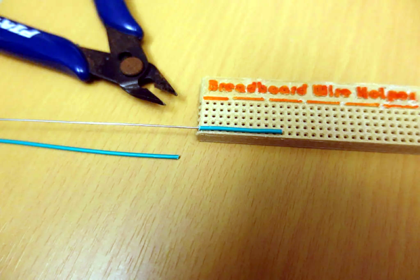
Need some breadboarding tips? We got you covered. Talking of bread, here’s an 8-bit TTL breadboard-based CPU in a breadbin.
Continue reading “Hackaday Prize 2023: Jumperless, The Jumperless Jumperboard”
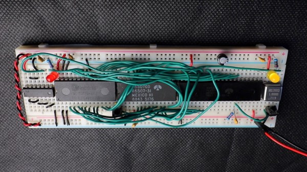

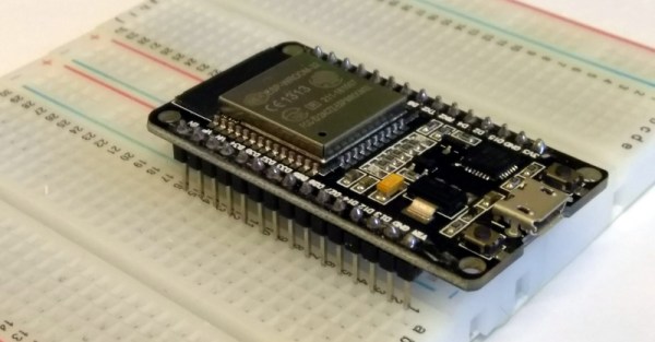
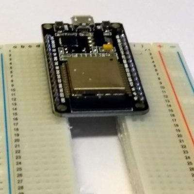 The solution came to [Luc] when he realized the center of every breadboard has no electrical connections, and was simply held together by a little piece of plastic. Yes, he took a hacksaw to the breadboard. This is technically a hack.


