If there’s one thing that brings hackers together, it’s the ability to build something for less money than it takes to buy it. It’s an exercise [Great Scott Gadgets] put to the test because he was playing around with some 18650 lithium cells, and had a huge need to put some tabs on batteries. This can be done by soldering, but to do it right you should really use a spot welder. Here’s the rub: you can buy a spot welder for about $250, and you can build one for a little less. So, the question: should [Great Scott] build or buy a spot welder? This wouldn’t be worth reading if he started off with an eBay order.
[Great Scott] designed this spot welder around a half-dozen supercaps, all securely held together with Kapton tape. This goes through a set of MOSFETs, and everything is controlled through an Arduino, a rotary encoder, and a dirt-cheap OLED display. It’s a simple enough circuit but a bit too much for perfboard, so [Great Scott] laid out a PCB and got a few boards for under $40. A bit of solder and some debugging later, and theoretically a spot welder was created.
After all that work, how did the spot welder work? Well, it didn’t. A slight misstep in the schematic meant this board didn’t have reference ground on the MOSFETs, so all this work was for naught. Of course, the only thing required to fix this board was a second board spin, as [Great Scott] probably bought more parts than necessary because that’s what smart people do. Still, he decided to cut his losses and shelve the project.
Thanks [BaldPower] for sending this one in.


And this is why you breadboard your circuits.
Which you can’t, with surface mount components. Oh well.
It doesn’t work too well with high current, fast power stuff either.
If it’s a board you plan to make a lot of there’s always breakouts for ants. They’re pretty cheap now. If parts are going to be bought just once because they’re expensive or something there’s always having some other smart people review your board and see if they catch anything you may have missed.
*breakouts for…not sure what that was supposed to say, just breakouts.
https://flic.kr/p/28yHLbG
You can, with deadbug/manhattan techniques. I very seldom attempt a first version as a PCB, because it’s almost always wasted time waiting for it, for something that needs to be revised anyway.
Building things yourself usually seems to only make sense when it’s custom, one off, high quality, or low quantity parts, yet battery packs seem to be the exception to this.
The price for say, even a relatively generic electric bike battery, even with the most basic battery management, is well higher then the raw parts. Usually it’s the other way around, a mass produced product is cheaper then the sum of it’s components. Why are battery packs different?
Liability/Engineering costs? While it’s not good if your personal lipo bank blows up for a commercial one to do so is going to be seriously bad news for the company.
Lack of demand maybe? For the really affordable ones you have to order in manufacturer quantities. Maybe there’s not enough hobbyist activity yet to get some competition into the field and drive down prices. Yet! The past decade has been very exciting in seeing the growth of affordable hobbyist and custom electronics. Maybe those bigass lithium batteries are also on their way.
For the odd knocking together of 18650 packs now and then, you don’t really need to go to quite so much trouble, a mid-sized motorcycle/jetski/skidoo battery suitable for a couple hundred CCA, starter solenoid, momentary switch and some decent cable.
https://www.youtube.com/watch?v=o4NaDMoEHxU
Thank you for this!
There’s plans floating around for spot-welders made from adding a high-current secondary to the transformer from a discarded microwave.
I made one from a microwave transformer once. It works if you can get good connections so that almost no voltage is lost in the wiring. Mine could heat metal to red-hot but I was never able to get good weld bond because I was wasting some power in the connections.
That worked great thanks for the info.
Nice. Yeah, he could also just use a starter solenoid to replaced those goofed MOSFETs, and keep the cap bank and most of the control circuitry.
Ugh, his soldering joints on the PCB are not great.
He always has quite a horrid soldering. I really dislike him teaching bad techniques to beginners / hobbyists.
Standards! We should have them.
ALL beginners should watch Bigclive’s demonstration of proper soldering technique.
Even experienced Makers could learn a few things. Starts around 1min into this video.
https://www.youtube.com/watch?v=nXkOxP5hka4
As I stated on the video comment (that nobody reads):
“The total amount of joules [energy] within the capacitor is dependent on both the voltage and the capacitance of the capacitor (as can be seen from the equation you’ve used). So if you have 400v 220uF capacitor and charge it from 15v source, you get peanuts out. The capacitor could hold way over *11700* times more energy if charged to full 400v… but few of us have high voltage power-supplies at hand and it’s dangerous.
Thus using high voltage capacitors in this type of a welder is not ideal and you want to use something like 50v ones so you can charge them to full capacity before discharging safely. :)”
So he’s not doing very good engineering to start with and tosses the idea of using capacitors out for no other reason than not being able to do the math.
And that there sure could cut a bit of cost from the DIY solution.
And if he is using a 15 volt source, then he could have went down to only use 25 volt capacitors, that usually cost a fraction of the amount compared to the same capacitance at 400 volts. Even though 50 volt capacitors also are fairly cheap in comparison as well.
He talked briefly about the high voltage caps, but the finished design is actually using 10F 2.7V superCaps (in series to getto 15V+)
So it’s not THAT awful.
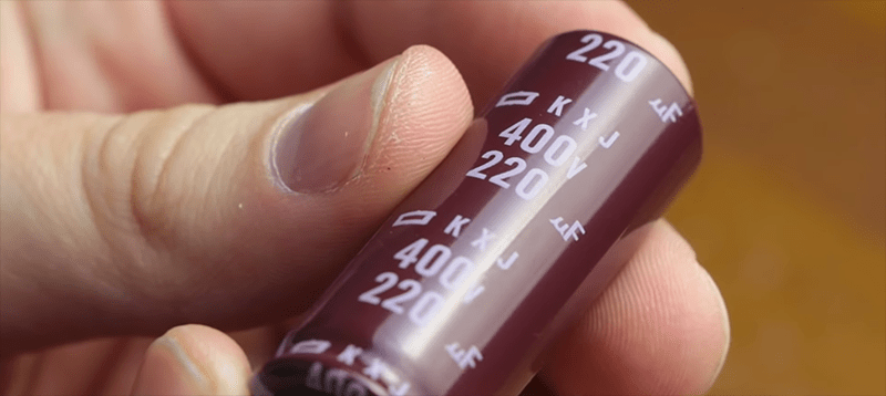
The cap in the lead picture is 220 at 400V, and is brown. Typical ATX power supply line supply side caps for world markets. Not a super-cap for sure. Us US’ers have way overrated caps in our supplies, they only need to be 200V. That’s good. The caps in the project don’t have visible specs but are green. Good practice has labels facing out, perhaps the other side is readable.
You are incorrect. Almost all modern commercial switching supplies above 100 watts or so – and almost certainly all modern ATX supplies – are power factor corrected. This is accomplished with what amounts to a boost converter, which takes the 170VDC rectified voltage of the 120V line and boosts it to 370-400V. Use a 200V capacitor in an ATX supply, even in the US, and you’re going to have a bad time.
Also, watch the video, the caps are labeled 2.7V/100F.
>This wouldn’t be worth reading if he started off with an eBay order.
I was under the impression his “build or buy” projects start with Chinese company contacting him about making a commercial with nice affiliate links – this is the moment outcome of the video is decided upon.
Now that it is understood how to fix this design, how much does it cost to DIY ?
Even with “new” EBAY parts.
I don’t think this is representative of DIY spot welders in general. The whole thing, from supercaps to ordering a PCB to an arduino with an OLED is overkill. A one-off spot welder for your own needs can be made much simpler, and for less.
Am I bad for saying that sometimes Scott’s other designs are a bit awkward as well. I remember a soldering station that used phasecutting of AC to regulate the temperature, thus requiring zerocross detection and a microcontroller triggering a Triac, while simple pwm of DC with a MOSFET would have done fine
Powering a heating element with DC works but is suboptimal because of electromigration which shortens the life of the heating element. See
https://en.m.wikipedia.org/wiki/Electromigration
Yeah, I guess if you’re going to suck at engineering and then give up instead of getting better, buying is the winner here.
But, since sucking at something is the first step to being sorta good at something, this could have turned into a good learning experience. Once he straightened out his MOSFET issues (which, judging from the schematic showing in the video, was going to take some doing — I can’t figure out how that was ever supposed to work), then he could start learning why you don’t run welding current through 22AWG hookup wire. Or he might have learned that (if I’ve found the right “DRL 2.7V 100F” capacitors) the 28 milliohm ESR of his capacitors doesn’t do too well with welding currents either. Since the capacitor bank will self-limit to less than 100A due to its own internal resistance, it would never reach the several hundred to few thousand amp currents normally used for spot welding batteries, and the welds would have turned out fragile or nonexistent.
If, on the other hand, someone wanted to do the math before designing the system, validate the circuit structure on a breadboard (at much lower current, of course), and build it sensibly, a very similar amount of effort could have yielded a useful tool. Oh well.
That’s the real lesson: Many are the times I’ve tried to be thrifty through DIY, only to look back in anguish because I ended up paying more and spending my own labor on what ultimately turned out a shoddy product.
But surely enough I started sucking less. These days I make many more useful products that I’m proud of than before, and some of them even save me a few bucks. Still spending too much time and refusing to account the cost of my labor, but you’ve got to spend your spare hours on some folly or another or else you’re not living to the fullest. That’s my excuse and I’m sticking to it!
There is a saying here that those with useful knowledge just use it, those without it become teachers. There is a reason, why so called “great” Scott is considered by his fans a good teacher. For me if he can’t make a working capacitive spot welder, then he is not Great nor Fair, he is at best [Mediocre Scott]…
Yes his soldering is rather poor. But that aside there is so many things wrong with that project it is no wonder it didnt work – The voltage drop across his interconnect wires would stop the thing working just on its own. just as a comparison heres a spot welder that works https://www.youtube.com/watch?v=bpYyEgpIo2k
This seems more like something built for YouTube views (clickbait) than for being a useful spotwelder.
But that’s the standard to expect from most trying to make a living off YT.
Can I say it? Can I, can I , can I?
Easier with a 555.
There’s a couple of examples on this site using a 555 as a variable one-shot pulse generator.
Yup! That’s the one feature I would add to the lead acid battery+relay welder posted above — a 555 for repeatable pulse lengths.
Which, of course, means the next version that shows up on Hackaday will do it with a Raspberry Pi, with a mobile app to control and monitor it, because what a spot welder REALLY needs is the ability to be compromised and become part of a botnet.
That has a certain prewar directness about it that I would hate to spoil with an IC.
Surely a pure electromechanical one-shot could be arranged instead.
Sigh. These days, I’m not sure what “prewar” means. I mean, which war? Sad.
Oh! I’ve got it: take an ancient camera shutter (I’m thinking Kodak Brownie, here), most of which already have electrical contacts for firing a flashbulb.
You can also buy a nicely engineered alternative to the ebay stuff from Frank Boeh at https://www.keenlab.de/index.php/shop/
He calls it the kWeld and kCap.
I bet that kit would make a fairly good little rail or coil gun. Love the ultracap package.
No doubt thete is an element of slaptick humor or rube goldburgishness, but I enjoyed and learned a bit from this, in an arena I likely will not venture. I am reminded of drawings where one tries to find what is different. He supplied the drawing with all the errors to find. Tha WestfW found a straw of redemption, I liked. Without errors, one doesn’t learn. In that vein, he “wrote” almost a tutorial. And my homemade ckt boarfs and breadboards work 1st time, evertime. You just have to be anal-lytical when transposing a schematic to “wire.” Waay back in lab, my partner and I also were in the first 25% done. Method brings speed, and no reworks.
I have one of these.
https://bit.ly/2ONp6k2
I bought it on a whim at far less than the going price as an open item in the clearance rack. I have never actually used it to pull a dent. I’m not sure I ever will as I do not have a professional paint booth so the necessary scraping through the paint will in most cases end up being more unsightly than the dent!
Anyway, I have thought about making a spot welder (mostly for battery tabs) out of it. But.. even though I doubt I will use it for it’s intended purpose I can’t bring myself to tear it apart and making it a sure thing that I will never use it to pull a dent.
Instead I have thought that maybe I can make some sort of metal jig that will allow me to use it as a spot welder without making any permanent changes.
But for now that’s just one of a million project ideas for the never arriving day that I have nothing more urgent to do.
Ugh! the link doesn’t seem to work. It is their stud welder. It’s a ‘gun’ that spot welds a stud onto a piece of sheet metal. It’s purpose is to weld a stud onto a dent on a car. Then a second tool is used to apply pressure on the stud so as to pull the dent out. then the dent is cut off and the spot needs to be repainted.
This is the ten dollar solution to a one dollar problem. Look in any older spot welder and you will not find any real electronics. The ones I have used had a simple timer to cut the power after a predetermined time or a bimetal thermostat that cut the power after a certain temperature is reached. A spot welder is about as complicated as engineering a short circuit.
Engineering a short circuit so that you can do it over and over isn’t trivial.
BUilding our own is much better