There are many reasons why one would want to measure voltage and current in a project, some applications requiring one to measure mains and even three-phase voltage to analyze the characteristics of a device under test, or in a production environment. This led [Michael Klopfer] at the University of California, Irvine along with a group of students to develop a fully isolated board to analyze both single and three-phase mains systems.
Each of these boards consists out of two sections: one is the high-voltage side, with the single phase board using the Analog Devices ADE7953 and the three-phase board the ADE9708. The other side is the low-voltage, isolated side to which the microcontroller or equivalent connects to using either SPI or I2C. Each board type comes in either SPI or I2C flavor.
Each board can be used to measure line voltage and current, and the Analog Devices IC calculates active, reactive, and apparent energy, as well as instantaneous RMS voltage and current. All of this data can then be read out using the provided software for the Arduino platform.
The goal of this project is to make it easy for anyone to reproduce their efforts, with board schematics (in Eagle format) and the aforementioned software libraries provided. Here it is somewhat unfortunate that the documentation can be somewhat incomplete, with basic information such as input and measurement ranges missing. Hopefully this will improve over the coming months as it does seem like a genuinely useful project for the community.
We’ve covered the work coming out of [Michael]’s lab before, including this great rundown on Lattice FPGAs. They’re doing machine vision, work on RISC-Vchips, and more. A stroll through the lab’s GitHub is worth your time.


schematic is here: https://github.com/CalPlug/ADE7953-Wattmeter/blob/master/Documents/Wattmeter_V4/WattMeter_v4.pdf (cut in half *fail*)
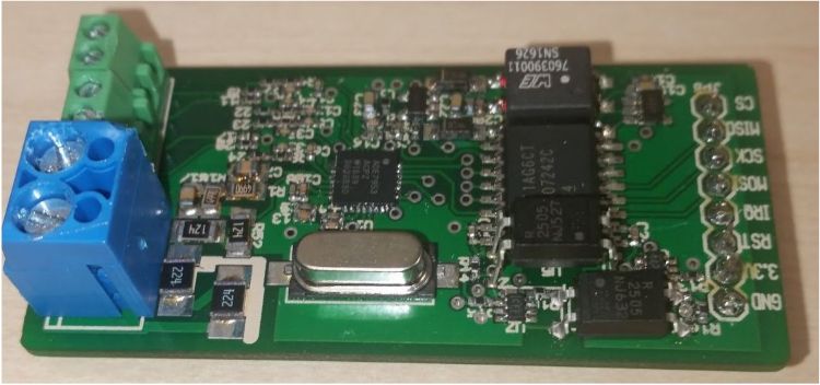
The interesting part are the IC:
main IC is ADE7953 as stated
powering the thing is done with SN6501 http://www.ti.com/product/SN6501 and PAM2305 https://www.diodes.com/products/power-management/dc-dc-converters/integrated-power-stage/buck-converter/part/PAM2305
isolation is done with ISO7241 http://www.ti.com/product/ISO7241C (2.5kVrms and 25Mbps, nice IC) and some optocouplers for low-speed-signals.
+some 74-logic
Only looked at the PDF images, but that single-phase PCB layout does not look like it has any creepage or clearance that is typically required for this stuff.
The three-phase layout appears ok, but the creepage would probably limit you to 230V at best where reinforced or double insulation is not required.
Measuring power for some stuff requires more than sampling a 100Hz or 120 Hz signal, which appears to be the intent of the design, as it seems to be based on the ADI application notes. Could not be used for stuff such as VFDs.
We got a ground fault detector at work (ungrounded 347/600v system), it was terrifyingly cramped and there were no cut outs in the board anywhere. It’s surprising how many “industrial” products will omit slots and isolation between low and high voltage.
Yeah, both designs are way too cramped for this to be safe. If board area is a premium do a stackup, one board with the potential connections and then another with the low voltage stuff like the current transformers. I have taken apart many power meters when I was working with a company that was developing a custom power meter for Bosch.
Reminds me of the HOPI meter bigclive on YouTube uses
Yes, that one includes the CS5463. It’s a similar all-in-one solution for energy measurement and analysis.
I’m not entirely sure, but the single phase board seems to have a voltage divider sized for 110VAC max, not RMS (110 *4.7/259.7 = 1.99V max input on the VP and VN pins is spec’ed at +/-2V). Unless my math is wrong, sizing this for 120V rms (170V peak) would require the 255k portion of the divider to become 394k (the 4.7k stays). This becomes 793k for a 240VAC system (in addition to rerouting to add clearance).
Does anyone know if something like a Talema AC1060 (60A $6.57 on digikey) would work as a current transformer? I’m not finding any specific specs in the documentation… I assume just adjust the 51 ohm resistors to make sure the voltage stays below the +/-2V limit? So with a 60A max on that part and a 1000:1 transformer ratio, change the 51 ohm’s to 16’s…?