The Silicon Labs Si4735 is a single-chip solution for receiving AM, FM, and shortwave radio. With a bit of hacking, it even supports single sideband (SSB). All you’ve got to do is provide it with a suitable control interface, which [Ricardo Lima Caratti] has done with his recent project.
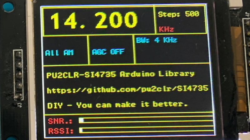
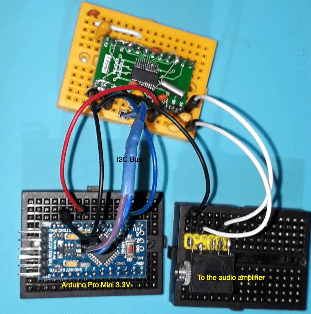 Using an Arduino Pro Mini, a handful of buttons, and a standard TFT display, [Ricardo] has put together a serviceable little receiver with a fairly impressive user interface. We especially like the horizontal bars indicating the signal to noise ratio and received signal strength. The next evolution would be to put this whole rig into some kind of enclosure, but for now he seems content to control the action with a handful of unlabeled buttons on a piece of perfboard.
Of course, the presentation of this receiver isn’t really the point; it’s more of a proof of concept. You see, [Ricardo] is the person who’s actually developed the library that allows you to control the Si4735 from your microcontroller of choice over I2C. He’s currently tested it with several members of the official (and not so official) Arduino family, as well as the ESP32.
The documentation [Ricardo] has put together for his MIT licensed Arduino Si4735 library is nothing short of phenomenal. Seriously, if all open source projects were documented even half as well as this one is, we’d all be a few notches closer to world peace. Even if you aren’t terribly interested in adding shortwave radio reception to your next project, you’ve got to browse his documentation just to see where the high water mark is.
We actually first heard about this library a few days ago when we covered another receiver using the Si4735 and [Ricardo] popped into the comments to share some of the work he’d been doing to push the state-of-the-art forward for this promising chip.


I didn’t notice if it was demonstrated, but id love to see RDS/RDBS implemented.
The RDS/RDBS functions are already partially implemented in the library I developed. I will do a demonstration soon. Thanks.
Way back in the early 80’s I was working at a plant that assembled cell phones. The old bag type cell phones. One thing that was interesting about these was the great care they went through in the case to isolate the parts from each other. The receiver, transmitter, logic board, and power supply were all on seperate boards, and each board fit in it’s own little enclosure in the case casting. This looks to be in 3 parts, so perhaps this will not be it’s own worse enemy, if the micro is shielded from the receiver. I also had a fidget for my trusty C64 that would decode Morse code and RTTY. The C64’s were not real well shielded and as soon as you turned the computer on next to the rig, the HF bands got a few points nosier.
Of course, those early cellphones were bulky, and used common parts, often thru-hole. I assumed that made for modularization.
Current cellphones have little to offer in parts, and not only are they on a small board, but nkt many parts either.
I was more making the point that the old cell phones used good RF design and kept the micro’s noise out of the RF. And FWIW, this was the first surface mount job this place did and it was done much more like through hole construction. There was a screening process but this was for a high temperature epoxy that was in the center of the components. The parts were glued on the boards and the boards were ran through the wave soldering machine much like through hole boards were soldered. Also, humorously the ESN was on a little PROM chip on it’s own board that was hand programmed, pop riveted into a little cavity in the case casting, and filled up with epoxy with just a little jumper sticking out of. There would be occasional manufacturing goofs and they would need to be removed. This turned out to be easier than it would seem once you did a few of them. A hammer, a wood chisel, and a hand drill to drill the rivet out. It was also worth noting that the chip connected to the board via a small ribbon so it was easy to pop another one in the potted parts place, and there was room in the cavity of the logic board for a loose one. Not exactly well thought out security, but the potted chip on the board did look impressive.
There are some settings in this project that need to be improved. This is a fact. Thanks.
At one time, I looked into these chips and found it odd you could get AM/FM/SW or AM/FM/WX nothing had SW/WX. So if you wanted to easily do shortwave and weather you would need two chips… unless you get really creative. I can only find one commercial radio that offers them both the ccrane skywave which also has the aviation band.
The Kaito Voyager Max KA900 does AM/FM/SW/WX, but doesn’t have the aviation band.
They might not say sometimes, just give a band from 108-200 and that’s aviation, weather, 2M amateur, and marine.
When I looked into a making a cheapish broad band receiver, these lost out to the chip sets used for SDR. For an extra couple of bucks I got a USB dongle that tuned 26-1750Mhz versus a bare chip with 4 bands. The SDR will tune to AM, but you need more processing power for filtering. And if your wanting LW (about 160Khz) making a up converter is not very hard at all.
This is off the top of my head, but in this day and age that up converter is easy. A OpAmp based bandpass filter with gain(we are dealing with ~150 – 280Khz here), mix it with a cheap CB crystal, bandpass filter it again, this one is a RLC filter, amplify(maybe optional) and then feed to the dongle. I know it’s brute force and a real designer could do better, but’s not really hard to build and testing it is fairly easy. The only gotcha to look out for is if your using a digital scope, your going to want at least 50Mhz bandwidth(more is not going to hurt). An analog scope can get by with 30Mhz(maybe 25) bandwidth. That is why I have two, a 25Mhz digital and if I suspect a problem, I can use my 60Mhz Kitisui(sp) to verify, but it’s big and hot so I only drag it out if I have to.
The si4735 ic is out of production so npt that easy to replicate this.
The replacement for this CI is the Si4745 (See Si47XX PROGRAMMING GUIDE; AN332), which has the same programming interface. It will probably run without adjustments on this CI as well.
I was hoping this would fly under the radar for a while until I can find a cheap source. I have the older version of the chip that I bought 9 years back. The datasheet mentioned custom DSP may be possible, and I have been holding onto it just in case. Sadly the chip version I have is not supported.
I am going to try my hand at a China store on ebay. Probably a waste of time and money.
Anyone attempted the NBFM firmware? I want to play around with the local CB bands as well as use as a tuneable IF receiver for the higher bands.
https://export.farnell.com/silicon-labs/si4735-d60-gu/rf-receiver-108mhz-20-to-85deg/dp/3105899
Funny how the price drops so much once you order a quantity of 250 or 500. But they only have 59 is stock, so..
The NBFM is also available in the same SSB patch. However, I did not implemented the NBFM functions in the Si47XX Arduino Library so far. I am planning to do this in the future.
Thanks Mr. Tom Nardi for the comments and references to the documentation.
Hi there,
Is it possible to get rid of the soft mute feature and have a smoth scanning experience when surfing the wavess without the punping sound?
Cheers!
Where do you get the various breakout boards for the si473x series?