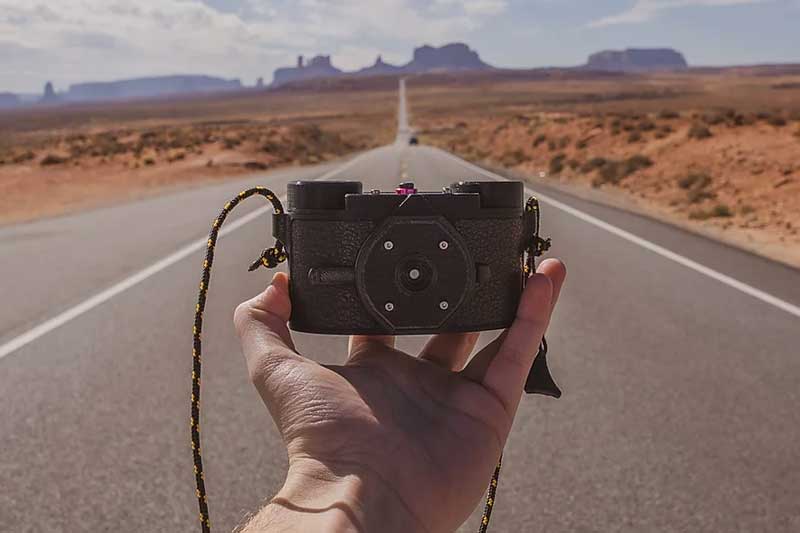
We’ve seen pinhole camera builds before, but this new one looks interesting. The Scura is a new open-source design for a pinhole camera that shoots on analog 35 mm film. It is all 3D printable except for a handful of screws, magnets, and the pinhole itself, which is laser cut. The cool and unusual part of the design, though, is the curved film holder, which produces 60 mm by 25 mm (2.3 in by 0.98 in) panoramic images that are sharp to the edges.
Most pinhole cameras produce fuzzy-edged images because the distance from the pinhole varies across the film plane. That throws things out of focus, but the sample images from the Scura look much cleaner and sharper because the curved film holder keeps the film at a constant distance from the pinhole.
The results certainly look promising, and the camera itself doesn’t look too difficult to build, as it is printed in just twelve parts. The only tricky bit is the pinhole itself: this has to be as small as possible, but also as round as possible. That can’t be done on a 3D printer (please feel free to prove me wrong on this), but it can be done with a laser cutter. Goodman Lab, the group behind the design, is offering a kit version for $84 that includes a laser-cut pinhole plate, 3D printed and other parts, and a hardware kit that includes the screws, bolts and pinhole plate for $38.
We’ve seen a few interesting pinhole camera builds, from the beer can model to the pocket watch sized, as well as a few great tutorials on building your own. Have you built a pinhole camera? Let us know in the comments and link to your photos!


How could a pinhole camera be out of focus? Though varying distance would distort the image in other ways.
True, it would just be a spherical aberration (But not the same one as spherical lenses) So curving the x plane only corrects it in that dimension. However with less y than x it’s less noticeable.
Two things:
diffraction effects (small pinhole)
defocus (too large a pinhole)
Ignoring diffraction, the smaller the pinhole, the sharper the image, as a smaller pinhole directs rays from a given direction in the object space to a smaller area on the image, approximately the same size as the pinhole.
A larger hole lets in more light, at the expense of focus in this way.
A small hole has much greater diffraction effect than a large hole (the area drops as the square of the diameter, the edge linearly).
For a given wavelength and distance between the pinhole and image, and other parameters such as exposure time desired, an optimal pinhole size can be calculated to maximize sharpness.
As you move from the centerline of the pinhole, other effects come into play. This design handles pincushioning in one axis. It is still subject to the pinhole projecting elliptically off-axis, among other things, but is probably about as good as it gets in simple, lens free imaging on film.
Nicely explained ! I was preparing to write something similar, but you did it far better than I would have !
There are numerous formulas to find the ideal diameter of a pinhole, but one that works really good is : Ø = 1/28 * square root (F)
With Ø being the diameter of the pinhole, and
F being the “focal distance”, i.e. the distance from pinhole to film / sensor.
This formula is a simplification that approximate this compromise of defocus and pinhole edge diffraction for the wavelenght of interest in photography.
Two articles on the subject for those who want to dive deeper : I’m sorry, for once they are french-written !
https://galerie-photo.com/loi-optique-stenope.html
https://galerie-photo.com/stenope-cercle-image-theorie.html
Is it really open source if you have to create a login to get access to the files??
Their privacy policy actually looks surprisingly benign, but if they’re not using the information (as they purport in the PP), why force someone to enter it in the first place??
“pinhole cameras produce fuzzy-edged images because the distance from the pinhole varies across the film plane. That throws things out of focus, …” betrays a gross misunderstanding of how pinhole optics works. Pinhole cameras don’t focus, and it’s impossible to “throw things out of focus.”
“the sample images from the Scura look much cleaner and sharper because…” because they chose the correct size pinhole for the size of the camera, balancing pinhole (spot) size against diffraction. For the ca. 60 mm distance to the film, the 0.3 mm pinhole is the optimum size (for visible light, for the pedants…).
I’d be skeptical you can reliably produce a 0.3 mm hole with a conventional cheap CO2 laser though. With tweaking and luck on any given laser, OK maybe. But I’m sure they are actually using a fiber laser for that hole.
Clever name too.
A laser cut hole… but but… you don’t need a laser to make a small hole… you can use “a pin” to make a pinhole. Pins come in various shapes ans sizes, I’m pretty sure that a simple sewing kit has a few suitable pins, but then it wouldn’t be a high-tech pinhole wouldn’t it?
And honestly, using light to make a hole to let through more light is a nice concept.
The whole will have little jagged edges that are not flat to the plane of focus and cause more refraction. A material you can poke with a pin is also likely soft enought that it won’t be flat to the film plane. But sure it will make an image.
It’s a hole. There’s no refractive material there. There’s no refraction going on, jagged edges or not.
Use a needle to make a dent in the soda can wall, then sand the bump on the other side flat. Push the needle deeper and sand the opposite side again. Check the hole dimensions with an old slide projector. Rinse and repeat.
Virtually every way of making a hole will produce a small bevel, or sharp edge, or anything that needs sending to at least 1000 grit to be clean. Except maybe chemical processes ? I wonder if anybody has already tried to electro-erode a pinhole. :D
Micro-drills the exact right size do perfect holes, but you have to use precise tools to use them. No hand-drilling here ! Drilling, then sanding to removes all micro-chips.
Better to use brass that will be chemically blacken once the hole is clean.
On the other hand, any hole in any materials will provide good enough results, unless you want to have the best system usable.
I’ve made dozens of pinholes using the technique Tonu explains : use a sewing needle to make a small dent in a sod can or a piece of thin brass, then sand the other side with fine sanding paper until the dent becomes a hole. And make several until you have one that match the needed diameter as close as possible. ;)
And if you don’t happen to have a fiber laser handy to make that hole, 0.3 mm is a #80 drill. Though a simple pin in aluminum foil will do the same.
Exaclty – have the case with a largish hole with aluminium foil over the top, and stick a fine needle in it.
When I was a kid, we had a subscription to National Geographic’s World Magazine. Specifically for kids, with all sorts of sciencey stuff. Part of what helped me grow into the geek I am. I recall vividly that one issue came with a punch-out, tape-together, papercraft pinhole camera designed for use with the old 110 or 126 film cartridges, I can’t recall which. Didn’t take the best of photos, but was absolutely amazing to this kid. Didn’t require a 3d printer, or a laser, or anything like that. For a glimpse, you can see it – 7th one down on this page – http://www.nmhistorymuseum.org/pinhole/Collection/CameraCollection/index.html
IIRC, it was 126. I, too, built it. Then kitbashed it repeatedly in a quest to improve things. When I took wave optics, I actually understood why things worked and didn’t.
There are people who love to take pictures, but the question is how to do it to get a good view?Or how to do it right to get a better photos.
…and suddenly I want a curved CCD sensor!
You might use a linear CCD sensor and have it move along a curved path. Hamamatsu makes some 512 pixel wide units, I’m sure they go bigger as well. Super simple to use, drive it as a shift register and digitize pixels as they come. Maybe worth it to use three of them along with some colored filters!
Well, the Kepler satellite has a curved CCD, and they aren’t using it any more, so you could go fetch that one :-)
Or, as [Michał] just said, use a linear sensor and physically scan it: these are readily available from plain old document scanners. You get 2500 pixels x 3(RGB) out of even a really cheap one. Search for “scanner camera” for many examples.
The idea that it takes a laser or some such to make a good quality pinhole is not true. Pinholes have been part of optics since the very beginning, and techniques for generating them have been around for hundreds of years. I found https://youtu.be/YLAO8K1rUWc is pretty good at explaining a reasonable way to make them with reasonable accuracy. The instructions that I used for years to make pinholes for optical testing comes from the November 1981 issue of Scientific American, in the Amateur Scientist column.
Thin piece of metal foil, pin through, sand the back.
Toss it in a scanner and count pixels to see how big it is.
Repeat on surfaces of different hardness until you get the desired aperature.