A dipole antenna is easy, right? Two wires, each a quarter wavelength long, emanate from a coax or other feedline. Unless it is an off-center dipole. The length is still the same, but you move the feed point to a different part. [KB9VBR] explains how this changes the antenna’s impedance from the nominal 70 ohms of a standard dipole.
Why would you want to do that? The trick is to find a feed point that has acceptable impedance on multiple ham radio bands. Most automatic tuners can handle a certain range of mismatch so using an antenna like this with a tuner can allow one antenna to serve multiple bands with no traps or switches.
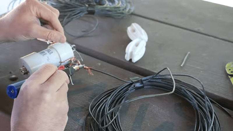
[KB9VBR] uses a 4:1 balun to convert the relatively high impedance to something close enough for a tuner to work with. A cordless soldering iron comes in handy for antenna work and in the video you can see a gas-powered iron making short work of the connections to the 14 gauge wire.
The impedance also depends on height and he suggests 30 feet, at least. Does it work? If you watch the end of the video, it apparently does. If you are in the mood for technical talk about ham antennas, you could do worse than watch this MIT video. If you want a novel take on why antennas work, you might want to read about the kink.


I was hoping he would go into balun selection and construction, but you can pretty much see why he chose this one..
https://mfjenterprises.com/products/mfj-913
Saw one fella making a “multiband” turnstile and he goes and uses a 1/4 wave loop of transmission line (coax) for the balun… which is not gonna work too well apart from prime frequency.
If you are interested, here is a link to the BALUN construction we made for the recent ham radio access to the old Radio Australia site.
https://ra.sadarc.org/#!/baluns
These BALUNs worked very well indeed.
A bit of info about the event… http://www.sadarc.org/
And here is a post I put on qrz.com… https://forums.qrz.com/index.php?threads/radio-australia-special-event-or-would-you-like-to-try-a-20db-hf-antanna.691991/
The first picture shows some of the curtain array antennas that we got to use.
Testing of these BALAUNs showed low loss and decent power handling capability.
Thanks!
When I build 1/2 Л diploes (10m, 11m bands..),
I always use a little stub made of coax cable,
which takes care of the correct transformation.
Otherwise, I might end up with a 1/4 Л essentially.
Many people don’t know about this apparently..
Same goes for coaxial connecting cables.
Ideally, they have specific physical length
in order to match the desired resonance
frequency of the antenna.
That’s in part also why SWR metres
sometimes display innacurate readings also.
(TRX internal SWR metre vs. ext SWR metre)
That being said, many hams can learn from SWLs.
They may be silent, but they know how to listen.🙂
Instead of a classical resonant dipole, the off-center dipole might be considered more of an untuned longwire with a counterpoise element.
You can always call EMR Corp in Phoenix AZ they are always willing to help even if it’s not their product
He should incorporate the 4:1 balun at the tuner and feed the antenna with open wire transmission line ditching the coax. It would yield much greater efficiency. Coax has pretty considerable loss away from it’s characteristic impedance whereas open wire transmission line will have negligible losses. It’s also very cheap to make.
I was trying to tell the difference between 300 Ohm feeder and coax on some receiving antennas, with balun relocation of course, for a relatively short 20ft run I couldn’t tell a difference. No change in receiver signal strength indications and no weak stations popping up out of the noise. Since he appears to be sitting right under his antenna, and will likely be similarly situated on a field day, I don’t think he’s got a long enough feed to worry about it much either.
The other thing about transmission lines are though that they are really sensitive to metal objects and anything that might be conductive if damp. So if you’ve got to go through a few walls, and be routed along the rain gutters or anything like that, then you may have enough obstacles to perfect transmission line performance that you may as well do coax.
Pre-amps, AGC, etc. would make it hard to tell any difference when receiving. The main differences will be noticeable in how well you transmit.
Matching is equally important for transmission and reception, in both cases the feeder should not act as an antenna.
In the case of transmission you could create a lot of interference.
in the case of reception if the feeder runs besides sources of interference like for example mains with PLC, led lights, SMP’s etc you could pick up a lot of interference making your setup unusable.
The balun at the feed point matches the 50 ohm characteristic impedance of the coax at the frequencies the antenna is designed for, so there is negligible loss at those frequencies, and you can use the antenna at those frequencies without a tuner. You can get common mode current on the feedline, though, so a choke before the feedline enters the shack is recommended. I used an OCF for years back when I had tall trees to hang it from. It’s a great multi-band antenna.