Cheap 433 MHz wireless switches are a tempting way to enter the world of home automation, but without dedicated hardware, they can be less easy to control from a PC. That’s the position [TheStaticTurtle] was in, so the solution was obvious. Build a USB 433 MHz transceiver.
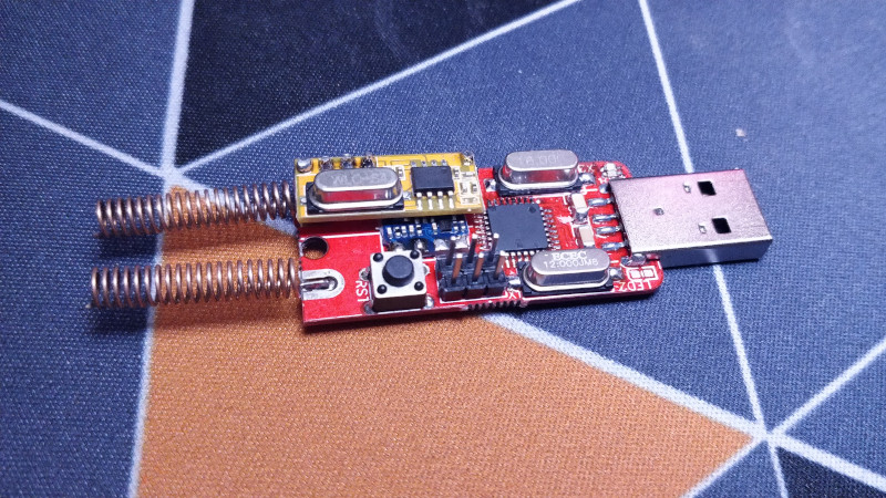
At the computer end is a CH340 USB-to-serial chip and the familiar ATmega328 making this a compact copy of the Arduino. At the RF end are a pair of modules for transmit and receive, unexpectedly with separate antennas. This device is a second revision, after initial experiments with a single antenna connector and an RF switch proved not to work. On the software side the Arduino uses the rc-switch library, while on the PC side there’s a Python library to make sense of it all. The code and hardware files are all on GitHub, should you wish to experiment.
The problem of making a single antenna transceiver is not for the faint-hearted RF engineer, as while diode switches seem on paper to deliver the goods, they can be extremely difficult to get right and preserve linearity. We’re curious that a transceiver module wasn’t used instead, but we’re guessing that cost played a significant part in the equation.
Over the years we’ve featured quite a few fascinating 433 MHz projects, like this TP-Link router conversion.


Is it a copy of an Arduino, or a copy of a copy? I thought only the bargain-bin counterfeits used CH340s.
On the other hand, who cares? The brand name is mud after “the untold history of Arduino” and the acrimonious conflict over the name. Plus, it’s a cool project regardless of what drives it. I wish laptops included ports for UART, SPI, etc. to make these kinds of interface boards more accessible.
But speaking of, what’s everyone’s favorite modern alternative? Espruino? Jerryscript? eLua? Embedded Python? PlatformIO? Other?
I, for one, don’t have any reason to use an alternative toolkit most of the time. The Arduino-environment works fine for the vast majority of my projects, especially since I don’t have this irrational hatred for C++ that many other people seem to have.
The few times I’ve used something else, it’s just been the official Ecliplse-based ST-toolkit for STM32’s because the Arduino-support for them is still rather buggy and lacking.
@Jenny List said: “We’re curious that a transceiver module wasn’t used instead, but we’re guessing that cost played a significant part in the equation.”
Hmmm… If cost was a big issue then why did [Samuel] use an Atmega328 micro plus a CH340 USB/UART chip? Instead he could have used an Atmega32U4 and dumped the CH340 USB/UART chip, its 12MHz crystal, and all the other parts that go with it. The Atmega32U4 has native USB and is the same micro-controller used on the Arduino Pro Micro.
Using PIN diodes as a TX/RX antenna switch has two drawbacks: 1. It’s more expensive than a piece of wire used as a second antenna. 2. An antenna TX/RX switch limits the device to half-duplex operation only. But in reality [Samuel’s] design with two antennas is probably limited to half-duplex operation anyway. The TX & RX antennas are so close together the receiver is likely overloaded (desensed) when the transmitter is operating.
“CH340 USB/UART chip, its 12MHz crystal”
Use a CH330N, it does not need an extra crystal:
https://www.youtube.com/watch?v=IIkoC_AOT6A
@zoobab says: June 29, 2020 at 2:58 am “CH340 USB/UART chip, its 12MHz crystal Use a CH330N, it does not need an extra crystal” [followed by embedded YouTube video link – sigh].
Thanks zoobab, I’ll take a look at this CH330N part. I see your link is an embedded YouTube video link. I’m not sure if you did this or maybe HaD did it automatically (for money?). Anyway, I’ll try posting the native YouTube link to your vid below here on on HaD, let’s see what happens…
Title: CH330N, USB-to-Serial IC for DIY projects, Arduino compatible [Mar 31, 2020]
https://www.youtube.com/watch?v=IIkoC_AOT6A
I’m done…
The direct YouTube video link did post here in this HaD thread (good). But time will tell if it survives “Moderation” over time.
Use a CH551G, it is as inexpensive as a CH330, and eliminates the need for two separate ICs. It is a USB capable MCU with no crystal required! Granted, it is 8051 architecture, so compiler options are more limited.
I second your choice of ATMEGA32U4 (or 32U2 which is even smaller), but if you are transmitting and receiving on the exact same frequencies, your radio will always be half duplex anyway, or am i missing out something here?
Hmm, has potential, reviewing mesh networks in that band but power limitations for legal use seem in the way to a degree…
Thanks for post :-)
How depressing. My WR703n is still sat untouched, 4 years after that article. On the bright side, it’s not lonely in the cupboard, having been joined by many more ‘to do’ projects…
Jenny – I did a fair bit of 433MHz reverse engineering starting around 1998 when the first of the cheap modules became available – particularly the SAW resonator based Tx devices.
I created several commercial products around SAW Tx and superregenerative (SR) receivers.
The superregenerative receiver has always been fascinating since it’s invention in the 1920s because of it’s low component count – and I reverse engineered several low cost wireless doorbells to investigate this ingenious class of receiver.
Users of the SRR will know that if you give it too much front end gain – it becomes an effective, but often undesirable transmitting device. However this dual capability of being both Rx and Tx – leads to some interesting low cost, low power and low component count transceiver designs.
There are some interesting SRR patents for micropower receivers ( notably McEwen – http://www.freepatentsonline.com/5630216.html) specifically one that used a specially biassed chain of CMOS inverters to act as a very high gain amplification stage, drawing mere microamps of power at under 1V operation.
I then realised that the front end detector stage of a SRR is effectively an RF oscillator biassed to the point where it is on the verge of oscillation – so I built a receiver around a SAW based Tx module. I used a PIC to act as the audio frequency sweep generator – that kept the Tx module constantly sweeping through its point of oscillation – and therefore maximum gain.
The intention was to build a minimum component RF transceiver stage for low baudrate half-duplex communication between microcontroller based sensor nodes. The sensor could idle at under 100uA consumption – in Rx mode waiting for a very low baudrate wake up call. It would then wake the mcu, and switch to Tx mode, sending its sensor data up to a range of 200m.
I got the receiver to work at 50uA from a 1.2V source and then the project was discontinued due to having to take on paid work
This project is from over 10 years ago (Nov, Dec 2009) but I documented as much as possible on my early blog.
It’s fascinating what you can achieve with a few transistors biassed into their linear high gain region with only microamps of operating current using 1meg bias resistors
http://sustburbia.blogspot.com/2009/11/radio-days.html + 2 subsequent posts
The best part about interfacing with 433 MHz widgets is your insurance policy.
Directly playing with mains current with unapproved devices is dicey from a liability point of view. With a UL listed (or equivalent) gizmo actually controlling the current, that worry goes away (though I’m sure you could be creative about a case where it might not). I have great luck with students using the “bridge the switch contacts on the remote” on/off method via a microcontroller operated relay. Inelegant and clunky, but it’s reliable and easily understood and can lead to other great things.
Cool device! I want it. Was about to build one myself for ages.
Hmm, or I port the stuff to the 32U2s i have floating around?
Difficult choice.
It survived. Yesss… Thanx HaD
Got any extras built? How much?