Adding an additional fan to your PC is usually pretty straightforward, but as [Randy Elwin] found, this isn’t always the case with the newer Small Form Factor (SFF) machines. Not only was the standard 80 mm fan too large to fit inside of the case, but there wasn’t even a spot to plug it in. So he had to come up with his own way to power it up and control its speed.
Now if he only needed power, that wouldn’t have been a problem. You could certainly tap into one of the wires coming from the PSU and get 12 V to spin the fan. But that would mean it was running at max speed the whole time; fine in a pinch, but not exactly ideal for a daily driver.
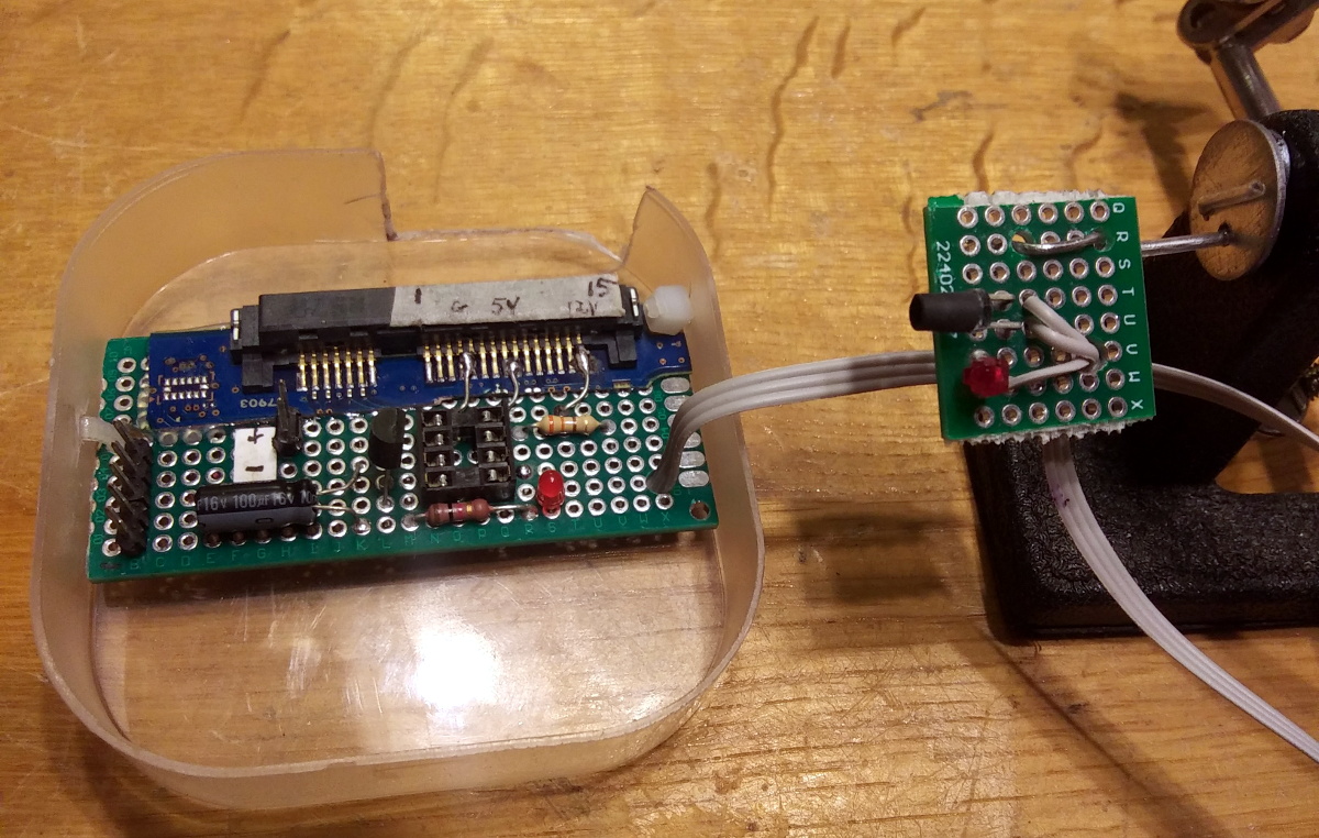
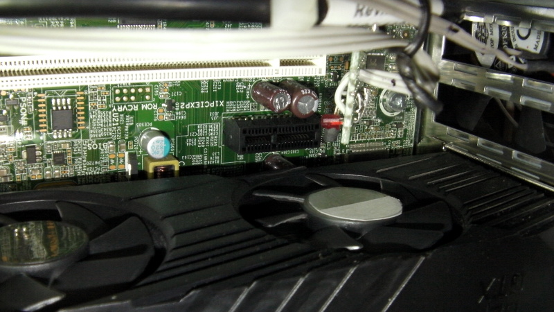
To get speed control, [Randy] put together a little circuit using an ATtiny85, an IR LED, and a LTR-306 phototransistor. The optical components are used to detect the GPU fan’s current speed, which itself is controlled based on system temperature. Using the GPU fan RPM as an input, a lookup table on the microcontroller sets an appropriate speed for the 80 mm case fan.
One could argue that it would have been easier to connect a temperature sensor to the ATtiny85, but by synchronizing the case fan to the computer-controlled GPU fan, [Randy] is able to manually control them both from software if necessary. Rather than waiting on the case temperature to rise, he can peg the GPU fan and have the external fan speed up to match when the system is under heavy load.
You may think this is overkill for a simple case fan, but compared to some of the cooling hacks we’ve seen in the past, it’s pretty tame.


Nice exercise, but overkill for fan control. Why not use some temp sensor to control speed?
4 pin fans can share a pwm signal, and if they are the same make and model the feedback pin from one is just as good as the other.
Why not read the article, instead?
I read that he used an IR LED and a phototransistor then before I read the rest I thought “If your fan is controlled by a smoke detector it’s a little late once it comes on isn’t it?”.
Maybe its to speed up the demise, by fanning the flames.
Is there a place he could have tapped into the SMBus for the PC? There should be pins on the PCIe slots. Host side software could then read temps from the system and send fan control messages to the new fan controller.
GPU output(s), RAM slots also have SMBUS to read off the parameters from an EEPROM.
Yep, the SPD data from DIMMs is a crucial part of the early boot process on a PC.
But leftover mining riser cards are cheap , and I think would make for an easy means to get a signal.
Maybe Windows has the interface blocked off. I see Linux has documentation on using the interface through.
https://www.kernel.org/doc/html/latest/i2c/smbus-protocol.html
I also see some devices that could be interesting:
https://www.analog.com/media/en/technical-documentation/data-sheets/1695f.pdf
https://www.maximintegrated.com/en/products/sensors/MAX6641.html
With all this, I wonder why people don’t try to exploit the SMBus more for their projects. Maybe I need to try building something to see what the pitfalls are.
DDR4 SODIMM adapter: https://www.aliexpress.com/item/4000126879484.html
Chances are that the 8-pin SOIC footprint is for an I2C EEPROM to override the SODIMM EEPROM
Corsair has their $40 Dummy DDR4 (with no memory) with RGB for them gamers.
PCIe riser is probably a better source for the SMBus signal as you don’t want extra stubs (PCB trace branches) on the SODIMM adapter to interfere with the DDR bus.
Win10 doesn’t have any API level access to the SMBus. Your usual PC fan/temperature monitor programs usual use their own ring 0 .dll to directly access known superio chips on ISA (via LPC). Not sure if there are open source version of these type of programs which would be a good start.
>In order to find hardware monitoring chips and temperature sensors, SpeedFan needs access to several resources on your motherboard. Some of them can be found on ISA. All PCs have got ISA, even if there is no ISA slot. Some other chips are embedded in the SuperIO chip. Some others can be found on the SMBus. In order to access the 2-wire SMBus (System Management Bus) serial bus, SpeedFan needs to communicate with other devices. SpeedFan recognizes and properly accesses several system bus.
BTW there is a program call “RW Everything” that let you access the raw info on a PC. e.g. BIOS, I/O, SMBus. Sadly no source code.
I mean.. if the GPU uses 4 wire fans, could have just tapped another write from that PWM pin.. it’s the same for all 4 wire fans.
And if it’s not controlled by a PWM signal but varying the voltage you could just feed that voltage into an ADC (after a resistor divider).
It is indeed PWM controlled on the GPU and it is very trivial to just use a Y-adapter and power two fans off it. Lots of Noctua fans come with the little adapter cable, even. This is such an over-engineered solution lol but I love over-engineered things in their own way too.
>One could argue that it would have been easier to connect a temperature sensor to the ATtiny85
The ATtiny85 already has built-in temperature sensor. Just need to put the uP where you’ll expect heat.
In the old days, some of the temperature controlled fans simply sense their own exhaust. If it gets too hot, run the fan faster.
Kinda funny that Microchip has its own line of fan speed controllers and OP isn’t using that.
Or y’know… the thermometer and PWM controller already located on his GPU. This solution could have been done with just wires.
idk, ive been wanting to go smaller than my elite 110 which has already seen some modding, removing airflow blocking panels. also dual 92mm fans on the right side of the case which dumps a tremendous amount of heat coming off the cryorig c7 cu.
i figure i can get a 140mm rad in there if i mod the bezel. aio would do the job, custom loop if i can justify putting a res in the space above my $500 video card *cringe*. but honestly its doing fine with air cooling.
Might just be me, but a optocoupler and a matching resistor bummed into the PWM drive wire of any four pin computer fan would be better.
Granted then he’d have to modify the wiring harness for the gpu fan or cobble a adaptor that plugs between original harness and pcb socket, but much more reliable solution that’s not susceptible to things shifting or something getting in front of the ir sensor.
That said, the approach he chose would be ideal for proprietary equipment with non-standardized cooling fan management, so still worthwhile to take notes of.
FYI: You don’t need an opto for this. You are running off the *same* PSU sharing the same ground.
The PWM signal on a 4-pin fan is 5V level.
https://www.electroschematics.com/4-wire-pc-fan/
>Intel specification (July 2004, Rev 1.2) defines the intended operation of a fan that implements the Pulse Width Modulation (PWM) control signal on the 4-wire fan interface. The following requirements are measured at the PWM (control) pin of the fan cable connector:
>PWM frequency: Target frequency 25 kHz, acceptable operational range 21 kHz to 28 kHz
Maximum voltage for logic low: VIL = 0.8 V
Absolute maximum current sourced: Imax = 5 mA (short circuit current)
Absolute maximum voltage level: VMax = 5.25 V (open circuit voltage)
If your opto is intended for accidental protection against hooking to the wrong 12V, then a 4.7K resistor in series with the signal before feeding into a microcontroller can offer effective protection *without* blowing up anything.
I mean you really don’t need isolation any more than the stock fan that plugs into the GPU’s PWM pins does. You can split off the power from there too, it’ll handle plenty of current for two fans. Done it plenty of times; noctua fans come with an adapter for it right in the box. Just a 4-element Y-cable with zero other components, neither passive nor active.
what I’d like to see is a way to keep the fans at exactly the same RPM, so that there are no beat frequencies in the audible range…
bingo.
with this, it only gets louder, not noise-ier.
thinking of noise as multiple harmonics (of ONE fan)
mixing and making further harmonics with another fans harmonics,
producing MORE harmonics and eventual LISTENER FATIUGE..
also, possible added benefit of destructive cancelation due to mis-alignment of point sound sources. ie it might actually get quieter in certain frequencies, but louder in others…
leading me to suspect this might sound more like a (very quiet) engine if he scaled it up with several more fans.