Home-based 3D printing is getting pretty unremarkable. Sure, printers aren’t as ubiquitous as, say, PCs. But you wouldn’t be any more surprised if your neighbor had a 3D printer than if you found out they had a drill press. In fact, sometimes the real value of 3D printing something isn’t to make a working part, but to make up something that helps you create other things using methods other than printing. That’s exactly what [iqless] does when he uses his printer to make some jigs to help him easily build shelves. (Video, embedded below.)
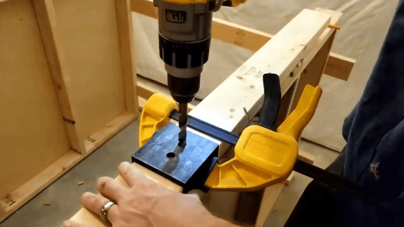
The issue is making dowel joints for the shelve’s feet. Sure, you could just drill a piece of scrap wood as a template, but with a 3D printer you can do better. Using OpenSCAD, it is possible to create a parameterized jig that fits exactly the job at hand.
There are several advantages to this approach. First, you can iterate on the design without having to rebuild a new jig. Of course, if a jig gets worn or broken, you can simply print another one. Finally, because the script is parameterized, it is easy to create a new jig for similar circumstances that have different dimensions.
If you have done a lot of OpenSCAD, you probably won’t see much new here, but if you haven’t created parameterized scripts, the video can show you how easy that can be.
We’ve looked at woodworking gadgets from 3D printers before. Or you can — sort of — print in plywood, if you like.


As an OpenSCAD fanatic myself, this video really ticks a few boxes for me:
1) He pronounces OpenSCAD properly
2) Makes you aware of how to get to the cheat sheet help right from the start
3) The example has the font size cranked up to a readable level
4) The benefits of sketching out the design before diving straight into writing the script
5) It covers enough of a practical application to get beginners thinking how it could be useful for them
Sure he could point out that F5 previews, F6 renders, the STL button generates what it implies, but on the whole it’s a pretty good beginner’s tutorial. Well done.
It’s an introduction to OpenSCAD, but one of the things that I use a lot is the ‘*’ and ‘%’ operators. Rather than commenting out a block of code that works for the purpose of disabling, put a ‘*’ in front of it. And rather than changing the color, use ‘%’ in front, and everything down will be rendered in half-tone (or whatever it’s called). Once I found those, that made testing stuff a lot quicker.
Indeed! They are very useful. I also have FACETS = 123; $fn = FACETS; at the top of my scripts as I find the $fn special variable (“face numbers” or “facet numbers” you might think, but “number of fragments” in the doc) by itself to be not at all self-descriptive.
Great watch , wish I seen it a few weeks ago. when i created a jig for Drilling holes in aluminum square tubing with out a drill press. its posted on thingiverse “Square Tube Drill Jig” made in OpenSCAD aswell
++ On printed jigs and OpenSCAD fluency. In this case though, a jig that helps you center the foot on the leg while you drill through both parts probably would be faster and simpler to use. And that could be made in a few minutes out of wood scraps and maybe drywall screws. Maye not as sleek though. Also, mixed-media jigs that use wood for the bulky bits and printing for the complex or precise bits can greatly speed up jig fabrication vs a completely printed jig.
Indeed, mixed-media jigs are a great way to trade off jig manufacturing time at the expense of some extra code to accommodate fixture holes, edge alignments, sockets, clamps and other requirements for the other materials, however that can all be learned in time.
Case example in point – last year I made a jig to cut a sheet of scrap brushed stainless steel for the surround fascia of a new kitchen cooktop. The stainless was too hard for my jigsaw to cope with and the edge that did get cut was awful.
The subsequent jig comprised 3D printed parts, a length of square aluminium RHS, scrap of angle steel, a bit of teflon sheet, and an air cut-off wheel tool. It guided the cut-off disc so smoothly along that, after a bit of draw-filing, was acceptably good and close to a guillotine edge finish in straightness.
It saved me about 300 AUD over having one made to fit. Of course from the time-is-money aspect, perhaps not so much, but I learned a lot and still have the jig in case I want to cut more long edges of sheet metal.
“Home-based 3D printing is getting pretty unremarkable.”
Running on our Brother™ 3D printer. ;-)
Great article. I do this a lot. Recently I printed a pocket drilling jig. It needed a piece of aluminium tube as an internal sleeve to strengthen it, but the 3D model provided the alignment for the jig.
Also, I say “open scad”. Bite me.
It’s zero pens CAD, because it’s all on the screen!!!1111 :-D
Was going to comment regarding press fitting a metal part of some sort like a nut that can be drilled out for a longer term or better quality jig like might be better for drilling into metal.
Good deal regarding the OpenSCAD overview. Next up on the list of apps to study application of.
I use flanged bearings in my jigs
Not just for metal – with protection the jig could be repeatable far longer so you could make your own home-brew version of the kreg jig for pocket screw in wood, in an infinite number of angles/sizes (they’re pretty great but I’d like more flexibility)
I drive a Ford…does this mean I can’t drive on the same roads, use the same fuel and get to the same places as Audi drivers?
I use Blender and Cura, so I can’t make stuff?
When the first few words of an article specify some software/hardware, I get cranky.
When the first few words are “How to…”, I get happy.
Too many tech articles lead with “Pruzah 3d Printer model XYZ-19a with FeelMeTouchMe v5.56 z-probe, v7.62 firmware by DoodleBug, using Ridges-of-Ink Ultraviolet PLA filament part number Q30.06…how to clear a jam!” rather than “Clearing filament jams from the Pruzah…”
I get it, everyone is addicted to branding everything under the sun these days.
Y’all feel naked if your title don’t name-drop your toys.
If the ‘Pruzah 3d Printer model XYZ-19a with FeelMeTouchMe…’ has some unique issues when it comes to clearing jams, then cool on having word-salad in the title.
But this aint the case.
Post after post with long titles naming the equipment and model number, but you have to ‘dig’ to find out what the post is really about.
There are big-name ‘pro-tubers’ who have posted series of articles on ‘basic 3d printer skills’ with “Pruzah 3d Printer model XYZ-a19a…” leading every title.
The ‘meat’ of the posts is almost completely generic, very little applies to only ‘Pruzah’.
Are y’all trying to sell printers, or teaching tech?
I’m not 100% sure what you’re getting at with this mantic rant, but the techniques described in this video are absolutely 100% specific to the way models are generated in OpenSCAD and aren’t directly relatable to Blender in any way. So…I guess you agree with the way it was presented.
The Prusa name on everything is a major turn off for me as well. He acts like he is the 3d printer be all end all. If anything he is holding back the community. Prusament. Cute. With an ego like that good luck.
Making fixtures and jigs, even if they are one offs, is a big advantage of 3D printing.
I mentor a high school FIRST Robotics team and we built a robot in the off season where we created jigs to drill the mounting holes for various electronics and other components. Mark the location of a single hole, clamp the jig, and drill the rest. First time we haven’t had to hog holes or swiss cheese some things.
I’ve done it for other stuff including things around the house.
Design is easy, the parts are cheap, the results greatly improved.
i’ve been doing this for a few projects, but so far i have included the jig as part of the end product…like i print a bracket with 2 angled holes for 1/2″ dowel to go through, and then i hold it in place to drill the appropriate angled/spaced holes in a plywood base, and then i slide the dowels through the jig and into the plywood, leaving the jig in place. i don’t need the jig for strength, but i designed it to be a spacer in the final product. (i could easily have used a chunk of wood instead)
http://galexander.org/x/guitarhangar.jpg
Never really thought about using a 3D printer to make woodworking jigs before but I like the idea. This makes me look forward to going back into the shed again when the weather gets warmer.
You could also use this same technique easily with Fusion 360, and – despite my software background – it’s going to be a lot faster in Fusion 360.
Fusion 360 also supports parametric design, so you can easily do the design one time and easily tweak the dimensions.
But, Fusion 360 is not free. Thanks, I’ll pass.
Fusion 360 also supports lulling their users into a false sense of security that their models are and will always be available to them in the cloud.
Sure, it has all the bells and whistles that OpenSCAD doesn’t. But I can live with that, knowing all my drawings/scripts efforts are 100% under my control.
“Person uses 3d printer for what 3d printers are for”
If the holes are the wear point where you need 10.5 hrs to print a new jig, why not leave room for shoulder washers?
That framing accuracy is a stupid idea and a waste of time. By the time he’s finished creating a jig, printing, printing. I would have done the project for it. Nobody will know that I was off by a millimeter or a degree following drywall and paint.