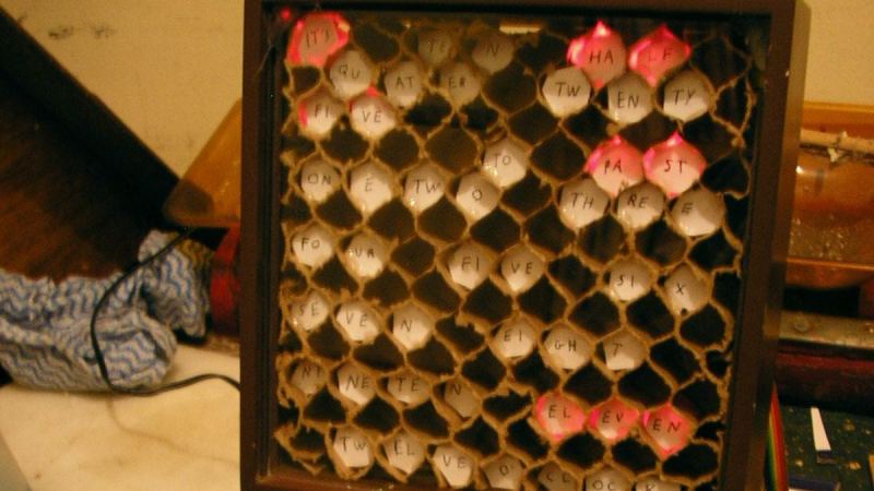
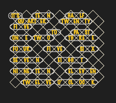
Self-acclaimed computer nerd [Kevin Koster] was tired of designing new TTL-logic clocks before finishing his previous designs. So he finally buckled down and completed this unique word clock, which uses only a handful of TTL chips. We can’t disagree with his friends who complained that they can’t read [Kev]’s handwriting, so perhaps this diagram will make it clearer.
Besides being a nice logic-only project, this will give an example to younger folks how much effort went into things which are so simple to implement today. We don’t see a Karnaugh map on the project page for sorting out the logic diodes driving the minutes LEDs. If [Kev] did it on the fly, as the rat’s nest of diodes on the schematic would suggest, we’re not sure whether to scold him or be impressed (he does redraw that logic very neatly on a separate sheet).
No worries about high speed wiring on this project. The main oscillator derives time from the 50 Hz AC transformer power supply, and outputs a reference clock signal of 16.7 mHz (not MHz), or once per minute. This is divided down to 3.3 mHz for the 5-minutes counter and again to 277 uHz for the hour counter. If you live in a 60 Hz power mains country, you’d have to modify the oscillator section. Or you could contact [Kev] on his site, as he is considering making this available as a kit worldwide. If you like word clocks, we’ve covered quite a few of them before, including this crazy-complex rear-projection one.


“No worries about high speed wiring on this project. The main oscillator derives time from the 50 Hz AC transformer power supply, and outputs a reference clock signal of 16.7 mHz (not MHz), or once per minute.”
Wrong! That misconception causes many subtle intermittent problems.
The speed is determined only by the transition time, not the period/frequency. If you want an anthropomorphic explanation, the circuit doesn’t care when the *next* transition occurs.
What do you mean wrong? Transition time? Of what?
The reference clock circuit is built as a frequency divider out of 74390 decade counters. The output frequency is the input frequency divided by a constant factor.
I suppose he’s talking about how any given oscillation is not guaranteed to take a specific amount of time. Just a guess though.
Well, again, it’s not a PLL oscillator but a frequency divider. I don’t see how the difference would cause any “subtle intermittent problems” though. The whole clock is just a pulse counter – it doesn’t care how those pulses are made.
Key search term: “signal integrity”.
Start your education by reading https://entertaininghacks.wordpress.com/2018/05/08/digital-signal-integrity-and-bandwidth-signals-risetime-is-important-period-is-irrelevant/
You still aren’t making any reason as to what your complaint actually is.
Tom is correct. In my mind, I was comparing this to circuits in the hundreds or thousands of MHz. Kev is using 74LS chips (you gotta zoom in close to see that), and that 390 counter has an upper limit of 35 MHz, for example, which dictates the rise times. In my experience this speed should be okay for using breadboards, vector boards, etc.
And in any case, if the problem is that the circuit is displaying erratic behavior because of signal reflections or other RF effects, signal coupling etc. the obvious solution is to slow it down instead of trying to design the wiring to properly support nanosecond rise and fall times.
So there’s nothing wrong with the initial assertion: no need for high-speed wiring here.
It might need a low pass filter on the first counter input. Over 40 year ago I had a mains referenced clock using 7400 series TTL chips. A 7490 divider is so fast it will count any spike on the secondary of the transformer like those induced by switching off a fluorescent lamp with a ballast. As a result it always gained a few minutes of time a day, while the synchronous-motor driven clocks kept the time perfectly. Today led-lighting and soft-starting vacuumcleaners might result in better timekeeping for 7400 series TTL based clocks.
It has a schmitt-trigger inverter before the counter to provide the hysteresis that filters out those rapid transitions.
A schmitt-trigger will transform a slow changing input into a fast changing output. A spike a few tens of ns long does not need to be that big to lower or raise the input across both thresholds and gets through the schmitt-trigger. Unless you insert a low-pass filter.
There’s also a zener diode at the input to the inverter, which is the pre-conditioning that takes 9 VAC to a square-ish wave that goes from -0.7 to +3.3 Volts. These zeners typically have junction capacitance on the order of 100 pF or so, which forms a low-pass filter with the 4k7 resistor with a cut-off around 300 – 400 kHz which is already removing all sorts of RF interference that might get into the circuit.
But more to the point, it’s unlikely you can even pass some nanosecond transients through the transformer, because the core isn’t designed for that. It’ll probably have difficulties passing few tens of kHz signals through a plain laminated silicon steel core.
You essentially have a massive choke at the input to the circuit anyways.
As old commercial mains powered digital clocks also often used the mains frequency as their timebase, I looked up the datasheet for one of the dedicated digital clock chips that were made and looked at their example circuit.
https://www.datasheetarchive.com/?q=LM8363D
They’re using a low-pass filter made with a 100k resistor and 10nF cap. With the 4K7 resistor in my design, and assuming the designers of the LM8363 knew what sort of real-world mains pulses to expect there, a 220nF cap in parallel with ZD1 might be a worthwhile addition.
“You still aren’t making any reason as to what your complaint actually is.”
Have you put in the effort required to use google as suggested, or looked at the reference?
What do you think is the maximum frequency present in a 74LS output? Hint: the usual rule of thumb is 5ns falltime => 70MHz.
You also ought to understand “ground bounce”, the cause, the effect, and what makes it worse/better.
The references you gave don’t explain what the complaint is. What you’re doing is giving us an “answer” and expecting us to deduce from that what the question is, and how it relates to the issue at hand.
I can google however much I want, and it still won’t explain what you want. Stop beating around the bush and trying to look smart by being vague, and say what you mean.
Er, I’m not complaining! My first comment indicates an error in Hackaday post; that’s all.
I’m not going to spoon-feed you by duplicating information and knowledge that is readily available elsewhere. You’ll have to work at increasing your understanding; sorry about that.
That is a complaint! What is the error exactly?
You can throw around references and vague hints all you want, but you haven’t exposed what the problem was.
As old commercial mains powered digital clocks also often used the mains frequency as their timebase, I looked up the datasheet for one of the dedicated digital clock chips that were made and looked at their example circuit.
(LM8363 datasheet link – omitted in the hope this post might finally go through)
They’re using a low-pass filter made with a 100k resistor and 10nF cap. With the 4K7 resistor in my design, and assuming the designers of the LM8363 knew what sort of real-world mains pulses to expect there, a 220nF cap in parallel with ZD1 might be a worthwhile addition.
As old commercial mains powered digital clocks also often used the mains frequency as their timebase, I looked up the datasheet for one of the dedicated digital clock chips that were made and looked at their example circuit.
https://www.datasheetarchive.com/?q=LM8363D
They’re using a low-pass filter made with a 100k resistor and 10nF cap. With the 4K7 resistor in my design, and assuming the designers of the LM8363 knew what sort of real-world mains pulses to expect there, a 220nF cap in parallel with ZD1 might be a worthwhile addition.
“That is a complaint! What is the error exactly? You can throw around references and vague hints all you want, but you haven’t exposed what the problem was.”
Sigh.
*Read* my first comment. Think.
Read Chris Lott’s comment (he wrote the Hackaday article).
Do your homework. If google can’t help you, read manufacturer’s application notes for TTL.
I guess you’re talking about high frequency ringing being counted by the circuit and progressing the time. I’m not sure though because you’re just being a supercilious ass. You keep saying “look at this”, “look at that”, and perhaps that would be fine if this were a classroom problem with one solution, but you are criticising a working machine that hasn’t exhibited any problems. If you have advice for the HaD readership beyond “RTFM” then give it in good faith, don’t try to convince us of your own superiority.
Exactly.
>Read Chris Lott’s comment
And I already responded to it: if the problem is that the high transition rates cause glitches because the circuit hasn’t been designed to deal with it, then the obvious solution IN THIS CASE is to add a bit more capacitance and resistance, and slow down the transitions rather than design the whole circuitry to support extremely fast rise times.
In other words, the original claim was correct: no need for high speed wiring on this project. Your complaint was simply grandstanding or besserwisserism.
In fact, it’s more likely that you’ll create a circuit with low-pass characteristics, rather than a high-Q circuit that keeps ringing with the signal. The problems generally start when you TRY to create a high speed circuit and then fail to address certain crucial points.
What those points are exactly? Oh, you should do your homework.
>Do your homework.
First you have to define the problem to the point that it can be answered. Just saying “It’s wrong!” is not enough.
In a previous job, I had a manager who used to bully people like that. He would take random photos from the factory floor, and in the monthly review he would show them and ask “What’s wrong here?”. People would come up with answers, and he would say “Good, I couldn’t see anything wrong, but I’m glad you found the problems.”
The question is, were they really problems, or just responses to the question?
Do your homework: find the point that proves me right, no matter how insignificant or irrelevant.
Somewhat disappointed. Read the word “discrete” and expected some old-fashioned transistorized logic, like pulse gates and frequency dividers based on monostables.