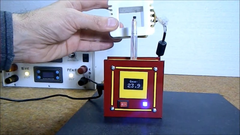
We’re used to Hall effect devices as proximity sensors in mechanical systems, used to provide detection of something that has a magnet attached to it. However it’s easy to forget that the devices that provide a magnet-or-not digital output are only part of the story, and linear Hall effect devices provide a handy way to measure a static magnetic field. It’s something [mircemk] demonstrates, with an Arduino-powered magnetic field strength meter that uses a UGN 3503U Hall effect device.
The circuit is extremely simple, comprising the sensor, an Arduino Nano, and an OLED display. This device is handy because its voltage output has a known relationship to the gauss level the sensor is experiencing, so while the accuracy of its calibration isn’t verified it can at least give a believable reading derived from the Arduino’s ADC.
The whole is wrapped up in an attractive case that looks as though it has been made from PCB material, with the sensor protruding on what seems to be the shell of a plastic ballpoint pen. It makes a handy instrument that provides a useful function for not a lot of money, so what’s not to like! Take a look at the video below the break for the full story.
Surprisingly such projects are few and far between here at Hackaday, however it’s not the first magnetic field measurement we’ve seen.


A Magnetic Field “streight” Meter?
Is this something that should be on every workbench?
I use a linear hall effect in my servo force sensors:
https://youtu.be/LoqGDTH75jY
UGN3503 is a Sprague part. Obsolete for many years. Available surplus. Allegro 1302 is the replacement. Also obsolete. Silicon Hall sensors have a lot of problems. The packaging typically has a couple percent magnetic hysteresis. They’re strain sensitive. Not good for anything analytical. The resolution he shows (0.01 Gauss) is far beyond what’s reasonable for a 3503. The uncalibrated sensitivity goes at least from .75 to 1.75 mV/Gauss. Temperature and supply variations are another +/- 50%. If you’re trying to actually measure a rare-earth magnet you need to go up to 10,000 Gauss (1T). Silicon doesn’t do that. Professional gaussmeters use Indium sensors. Silicon sensors are OK for switches and speed sensors.
Interesting. Thanks for sharing, I love coming to the comment section for:
1) laughing at the usual rambling around 555’s, Arduino, 3D printing
2) broadening my knowledge.
Cheers, Jan
People use Silicon Hall sensors because they’re cheap. Not much point to an instrument that’s maybe +/-50% with 5 digits of resolution. They’re not really suitable for a lab instrument. OK for limit switches and motors or maybe digital pots and that sort of thing. They do not work well for a compass. Those work around a half Gauss full scale and that’s in the noise for Silicon. A compass needs magnetoresistive or fluxgate sensors. Silicon is also not good at high fields like a kilogauss or more. You’d want that for speakers and characterizing magnets. A lab instrument would use Indium, Gallium Arsenide, rotating coil or more exotic stuff. Some of those are not actually all that expensive for the raw sensor but the supporting circuitry is a lot more than a dollar.
Sounds like you should be designing one for us slackers! I look forward to an article about it.
Picked at random: The SiLabs Si7210 [1] is a Hall effect magnetic sensors with 0.1% linearity and an I2C interface, no Arduino ADC to tame. The Si7210 tops out at 0.2T. Eval bords for the series are $29 bucks each. The Si7210 at Mouser is $0.82 in unit quantity, in production with plenty of stock.[2]
* References:
1. https://www.silabs.com/sensors/magnetic/si7210
2. https://www.mouser.com/Search/Refine?Keyword=Si7210