The average punter shunts audio around with analog 3.5 mm cables, RCA jacks, or Bluetooth on a regular basis. A useful standard that hasn’t really bothered most of us is S/PDIF, standing for Sony/Phillips Digital Interface. It’s a useful way to pump digital audio around over copper cables or optic fiber. [Andrew Jeddeloh] got curious about the standard after contemplating some long cable runs in his home, and decided to try decoding it.
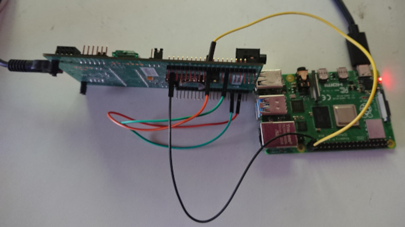
The target for [Andrew]’s development efforts was the STM32L476 Discovery, which had no SPDIF decoding hardware on board. Instead, [Andrew] tinkered with the peripherals he had to see what would work. In the end, a cavalcade of internal timers were daisy chained to allow the microcontroller to recover a clock from the self-clocked S/PDIF signal. This was then used to generate a clock to sync up the onboard SPI hardware to actually read in the 16-bit PCM data from the S/PDIF signal.
[Andrew]’s original broader plan was to pipe the S/PDIF data to the onboard I2S DAC, though he struggled manipulating the remaining resources on the STM chip to do so successfully. Anyone wishing to have a crack can take a look at [Andrew]’s code over on GitHub. If completed, the STM32L476 would become a useful analog endpoint for S/PDIF streams, allowing you to pump tunes digitally over long distances without signal degradation. If you know the key to getting it done, sound off in the comments! Alternatively, if you need to get up and running more quickly, the Teensy platform has you covered!


Looks like a painful way to replace a CS8416
Yes, this is a solved problem. SPDIF to DSD would be neat.
Oh for sure it was, but it was mostly a “because I can” project not a “because this is a good way to solve this problem” project.
Just off the top of my head, this sounds like an application for the programmable I/O units in the RP2040 microcontroller.
When I looked at the pre-made PIO programs on the dedicated github, I believe ther was indeed one for that protocol.
interesting but… why not using another STM32 with an wardware SPDIF RX like the STM32F446RE ?
It also comes in the Nucleo form factor, pretty inexpensive
A small FPGA would do aswell :)
Indeed. In school I coded a basic SPDIF mixer core in VHDL. It’s not much more than a deserializer. The project had multiple SPDIF inputs and added them all together then re-transmitted the output to SPDIF. Crude volume control by bit-shifting (obviously very rough). Can’t remember what FPGA we used, but for that time I don’t think it was considered small. 24 bits of audio at 96 kHz and 8 channels input is not a trivial throughput.
I used this STM32 because its what I already had. I could have also avoided a lot of trouble with GPIO pins not being available too if I had used a different board.
I actually have a very similar project I started a few months ago, just on the Bluepill (STM32F103), with the goal of having a optical SPDIF to USB audio receiver.
Initially I just bought a cheap USB audio interface, but couldn’t get the optical input to work on Linux (and most of the other options with optical SPDIF input were much more expensive).
In my case I’m using a less elaborate timer setup as I do the frame aligning by bit shifting instead of syncing the SPI block to frame start.
And I use a lookup table to do proper biphase-mark decoding including detection of syncword, framing and parity errors, which looks like this:
uint32_t x0 = spdif_dmaring.peekword(0);
uint32_t x1 = spdif_dmaring.peekword(32);
uint32_t state = BMC_DECODE_START;
uint32_t tmp = x0;
uint32_t out = 0;
state = bmc_decode[(state & 0x700) | (tmp & 0xff)]; tmp >>= 8; out >>= 4; out |= state <>= 8; out >>= 4; out |= state <>= 8; out >>= 4; out |= state <>= 8; out >>= 4; out |= state <>= 8; out >>= 4; out |= state <>= 8; out >>= 4; out |= state <>= 8; out >>= 4; out |= state <>= 8; out >>= 4; out |= state << 28;
if (state & 0x400) spdif_framing_errors++;
if (state & 0x200) spdif_parity_errors++;
Ok, that got mangled, here is the gist instead:
https://gist.github.com/ranma/441c47cd3e7b6ecf727504a797b1bb15
I considered using a LUT for decoding but decided against it since the code I have is fast enough and generating the LUT seemed like just as much work as writing the code to decode it without one. A LUT would be cleaner IMO but I was getting tired of the project at that point so didn’t bother.
About those long cable runs…
I’ve had success with using RS485 transceivers and pushing the signal through CAT-5 cable.
You can also combine this with 100Mbit/s Ethernet, as that only uses 2 of the 4 twisted pairs.
On top of that I’ve made a simple network I call “Mumarnet”. It also uses a wire pair for 24Vdc and a wire pair for 115k2 data in packets. All together it’s a pretty capable home automation project. I have two mumarnet nodes that each control some logic to make analog audio out of S/PDIF and a PGA2311 for volume control.
Because RS485 transceivers can be turned off, you can have multiple audio sources, as long as you make sure just one is on at any given time. You can also put a lot of RS485 transceivers on a single cable, so you can distribute audio through the whole house in a simple and reliable way, and with no latency issues whatsoever.
Oh, wow. You can get audio through RS485? It’s amazing to think all that industrial control hardware that can also serve as HiFi.
You can put anything digital through 485. The only limit is the bandwidth which can be fixed by adding more pairs.