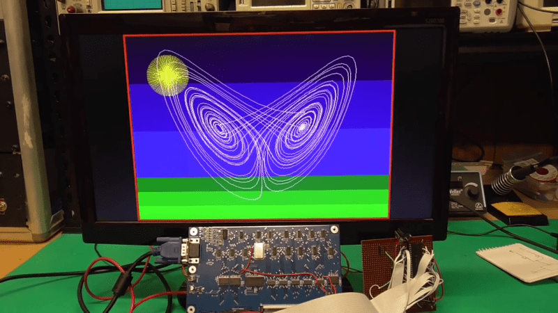
Feeling nostalgic we presume, [Glen Kleinschmidt] set out to build a 640x480x64 VGA controller card from discrete logic chips. If we ignore the 512Kx8 Cypress SRAM video memory, he succeeds, too — and on a very readable, single page A3 schematic. The goal is to interface some of his older 8-bit machines, like the TRS-80 Model 1 and the BBC Micro, but for now he’s running a demo using a 20+ year old PIC16F877 micro.
[Glen] provides all the schematics, Gerbers, and C source code on his website should you be inclined to reproduce one for yourself. He has three versions in the works, with various capabilities (there’s a table on his website). As an alternative, one could always use an FPGA or a custom-built chip such as the SSD1963 to generate video for these micros, but sometimes the urge to go retro is too great to resist. We get the feeling that for [Glen], this is a project unto itself, and being able to interface it to his 8-bit computers is just a convenient excuse.
This isn’t [Glen]’s first retro project, either. Check out his analog computer “bouncing ball” project we covered back in 2017. Have you struggled with the build vs. buy decision, and how do you decide?


This is really well done. I like the timing domain fix U5 U6 U7. Bonus point do the raw SR latch U21.
I kinda got freaked out with the 1 indexing U2 (P0).
I done may of these in VHDL (yeah cheating) so I may have some things you might like too try.
640×480 is aspect ration 4:3 so it gives you square pixels/tiles on a 4:3 screen. None of the very early computers like the Trash 80) had square pixels/tiles that I can remember.
Modern VGA monitors recognize various VGA standards by sync frequencies, sync polarities, active horizontal “window” and number of vertical lines. ie they ignore pixel clock. So as long as you get the other things according to a standard then your free to use whatever horizontal resolution you choose. This helps with memory utilization. This also gives the freedom to better utilize memory by choosing a different aspect ratio. Most monitor now are 16:9. You can use a 4:3 aspect standard to over-scan to a 16:9, the monitor doesn’t care.
I see you chose the age old CGA derived standard for VGA. ie 25.175MHz clock, this standard was closest to PAL/NTSC.
I find it easier to use the 800×600 72Hz 50MHz standard.
If you get stuck with propagation delays (you may have done this already) increment the counter on say the rising edge of the clock and load on the falling edge.
One thing that did bother me ,was that the memory page window for the type C board is less then a full line of data. The Z80 has some quite fast instructions like LDIR etc. These kind of have to break in the middle to update the page address.
In VHDL you can also do a lot more like making the memory addressing more linear or sliping the access window in two, one for CPU and one for VGA (no flicker) but that kinda gets overboard with 74xx.
One thing you may consider that doesn’t cost extra chips is to change the addressing scheme so that each sequential 8 bytes of RAM represents an 8×8 pixel block on the screen. Just a bit of jumbling up the counter to RAM address bus.
Another thing, your old <5MHz CPU will really struggle with resolutions like 640×480. It a slot of CPU clocks to update things on the screen. I find it better for resolutions like 320×480 (which can be equally done at this standard 25.175MHz just drops to half and each line is repeated to get the total line count. Or even 400×300 using the standard (50MHz) that I mentioned earlier. This can be stretched to WXGA.
This is really well done.
> ie they ignore pixel clock.
CRT monitors doesn’t care about pixel clocks, but LCD monitors still generate an internal pixel clock for A/D sampling to drive the scaler that converters to native pixel resolution. If you have lower resolution, it’ll treat the large pixels as n consective pixels having the same colors.
I’m not sure why he didn’t use 3:3:2 colour, the data is there, all he needed was a few extra resistors. The human eye is less sensitive to blue light, so 3 bits for each of red and green and 2 bits for blue works quite well.
while a bit more complicated SIH (Saturation Intensity HUE) based color should be more useful as it can be indexed using 8 or 16 bits.
Man, that’s cool. I would probably have tried a 6845 CRTC (which is itself pretty retro, at this point) but idk if that’s even feasible for VGA. Rather suspect 6845 tops out around 16MHz. Anyway, strictly MSI, like the TRS80 M1? Hardcore!
The 6845 is acient N-MOS technology – it runs at blazing slow speed of 2.5MHz. :P There are faster versions by Moto back then, but none of them run at double digits MHz.
What people usually do is to use it to address the individual characters and have separate parallel to serial converters that blast the individual pixels at higher speeds and feed a clock divider to the 6845. i.e. you have 8 pixels per character, your 6845 runs at 1/8 pixel clock speed.
Yeah, the 45 is just an address generator. You always had to supply your own shift register. RS-170/NTSC horizontal lines were 63.5 us (near enough) so you’d set the 45 to fit 127 chars per HSync, use 80 of those for active display, and access memory at 500 ns (2MHz) to get the characters. At 8 bits per memory access giving 8 pixels, the pixel clock would be 16MHz in that example. Which is probably why that number stuck in my head.
So.. to get a pixel clock up around 30MHz, if one were really committed to using the old 6845, with memory access limited to 2MHz, would require widening the data path. Haven’t worked the numbers enough but seems like one might get there with a 16 bit data path. Hmm. Maybe I’ll run the numbers later.
(Fwiw, I think the CBM PET 8032 used the 16 bit data path to keep buffer accesses at 1MHz, when in 80 col mode)
A 2.5MHz clocked 6845 would have a 400ns cycle time. Back in the day, you can probably get the faster120ns RAM (to store text) cycles + 250ns EPROM for the font table look up and the rest for the chip delays. So the 2.5MHz wasn’t quite a limit.
You can get a 2nd source Hitachi 3.7MHz HD6845S (MC68B45??) and that would get to just a bit shy of 30MHz with a 8x pixel clock. HD6824R (MC68A45??) is 3MHz, so probably can be overclock or just run at rate and let the modern day monitor sync to it.
Thanks for mentioning the 6845, after a bit of digging around I found this calculator! https://mrboot.de/mc6845.php
Is it complying with standard PC VGA graphics and text modes, or is it just putting out a picture that most VGA monitors can display?
That would be the latter. Text modes etc would require rather more hardware than this (there’s no character generator ROM to start with).
VGA or video graphic array are used to connect to the regular computer monitor. We can make the VGA controller card using the discrete logic chips and the SRAM of a certain memory. The video card design explained in the given article is built out of 74 series derivative cmos logic. Such video card is used in the old school computers with 8bit processor. The vga card built from 74 series logic gates and the 8 bit microprocessor usually support the resolution upto 640*480*64, which is sufficient to build videos and retros in the 8 bit computers.
“I see you chose the age old CGA derived standard for VGA. ie 25.175MHz clock, this standard was closest to PAL/NTSC.”
I think the ease of implementing this specification is reflected in the simplicity of my design. I’ve complied entirely with the original IBM timing specification: http://gunkies.org/wiki/VGA
The 1:1 pixel aspect ratio for the 640×480 (Card A, B) and 320×240 (Card C) resolutions is exactly why I went that way. No need to do any additional scaling calculations to fix the aspect ratio when, say, plotting trigonometric functions (like the polar roses of my demo). All of my VGA-compatible widescreen monitors have a 4:3 mode and I didn’t want a widescreen card design incompatible with my CRT monitors.
The reason for the reset to 1 (U2 P0) is because counting 1-800 rather than 0-799 makes for the simplest fully synchronous decode logic for all of the horizontal timing. And there’s a hardware hack open here for anyone that might replicate the design – lift P0 and ground it instead – you’ve now slightly violated the timing specification but have increased the horizontal resolution to 641 pixels.
“One thing that did bother me ,was that the memory page window for the type C board is less then a full line of data.”
You must be referring to the example address expansion register I posted, which isn’t part of the video card design and was only an example of how little main processor address space might be use to control the cards if you really needed to go that way. However Card C shift pixels at half the clock frequency and addresses the 1/4 size RAM (compared to Card B) accordingly. A 512 byte page is assigned to each line (320 bytes map to the screen, the rest are available to be utilized as System RAM). So the “memory page window” is indeed one full line of pixel data.
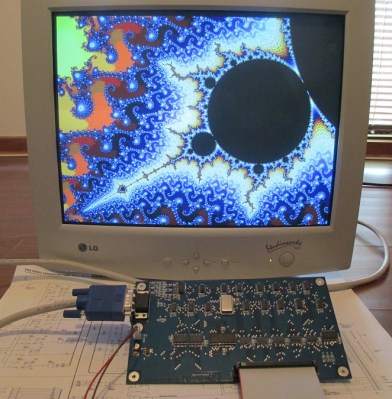
Card C is intended for slower processors but even still, for my own intended use, I’m not particularly worried about addressing 640×480 pixels with any of my old slow machines. I can write programs to compute fractals, Mandelbrot Sets and three-dimensional chaotic attractors with 2D/3D protective transformations and the CPU overhead in most instances is predominately in doing the calculations, not in writing to the display.
A 1MHz Z80 is fundamentally no less capable of doing any of the above than is a 20 MHz Z84C – The only difference is you might be able to drink half a cup of hot coffee whilst your math algorithms are plotted to the screen. But so what? Still a lot more interesting overall than doing little more with your vintage computer hardware than occasionally loading and playing Frogger or some Space invaders derivative (as fun as that might occasionally be).
I spent endless hours back in the day plotting graphics and trig functions on my BBC Model B in Mode 0 (640×256 2 colour) and Mode 1 (320×256 4 colour) and there were atleast half a dozen books published on the topic of generating high-resolution graphics with this machine, despite the machines pedestrian pace at writing to the screen in the higher resolution modes.
Hey editors, people are starting putting SEO links in the “website” field of the comments.
I now have this video card interfaced to a TRS-80 Model 1. Full project write up here:
http://www.glensstuff.com/trs80vga/trs80vga.htm
Wow, this is very impressive. My hard drive is littered with several false starts at exactly this, but I have never had the time or perseverance to finish any of them. You clearly have a grasp of the nuances of “getting things done” with TTL which is getting more rare with time. Back in the day I wire-wrapped custom processors with 50MHz clocks in 74LS (and 74S or even 74F where needed) and burnt my fingers on the chips.
As a community we need to publish more works like this (and your other projects) and get the youngsters (I mean that fondly) going on this sort of design. You’ve inspired me. This is art.
Time was, I would have whipped out my electric wire wrap gun and a good proto board and built one by hand!
“This video is unavailable”
sadtrombone.com womp womp womp womp waaaaaaaaaaaaaaaaa…