VGA Graphics Card In 74xx Logic

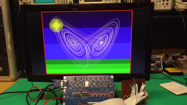
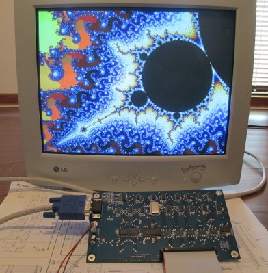
Feeling nostalgic we presume, [Glen Kleinschmidt] set out to build a 640x480x64 VGA controller card from discrete logic chips. If we ignore the 512Kx8 Cypress SRAM video memory, he succeeds, too — and on a very readable, single page A3 schematic. The goal is to interface some of his older 8-bit machines, like the TRS-80 Model 1 and the BBC Micro, but for now he’s running a demo using a 20+ year old PIC16F877 micro.

[Glen] provides all the schematics, Gerbers, and C source code on his website should you be inclined to reproduce one for yourself. He has three versions in the works, with various capabilities (there’s a table on his website). As an alternative, one could always use an FPGA or a custom-built chip such as the SSD1963 to generate video for these micros, but sometimes the urge to go retro is too great to resist. We get the feeling that for [Glen], this is a project unto itself, and being able to interface it to his 8-bit computers is just a convenient excuse.

This isn’t [Glen]’s first retro project, either. Check out his analog computer “bouncing ball” project we covered back in 2017. Have you struggled with the build vs. buy decision, and how do you decide?

Continue reading “VGA Graphics Card In 74xx Logic”

74-Series Clock Gets A MEMS Heart

[Erik van Zijst] has had a long career as a programmer, but lacked an understanding of what was happening at a bare metal level. After building a few logic gates out of transistors to get a feel for electronics, he set out to build a working clock using 74-series logic. Naturally, it was quite the adventure. 

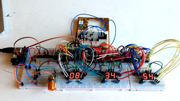
The project starts out as many do on the breadboard. The requisite BCD counters and 7-segment displays were sourced, and everything was connected up with a cavalcade of colorful hookup wires. A 32.768 KHz crystal was pressed into service to generate the clock signal, divided down to get a 1Hz output to drive the seconds counter that would then run the entire clock. [Erik] then had to learn some more practical electronics skills, to deal with debouncing buttons for the time setting circuit.

With the clock now functional, [Erik] decided to take things further, aiming to build something more robust and usable. An automatic brightness control was created using a 555 to run a crude PWM dimmer for the LEDs. Additionally, a PCB was designed to replace the temporary breadboard setup. This led to problems with the oscillator that [Erik] couldn’t quite figure out. Rather than continue on the same path, he changed tack, instead replacing the quartz crystal with a modern MEMS oscillator that solved the problem.

It’s a great look at how to construct a working clock from bare logic, and one that serves to remind us just how complex even a seemingly simple device can be. We’ve seen other from-scratch builds before too, like this 777-transistor clock, or this attractive stacked design. Video after the break.

Continue reading “74-Series Clock Gets A MEMS Heart”

Pushing Pixels To A Display With VGA Without A PC

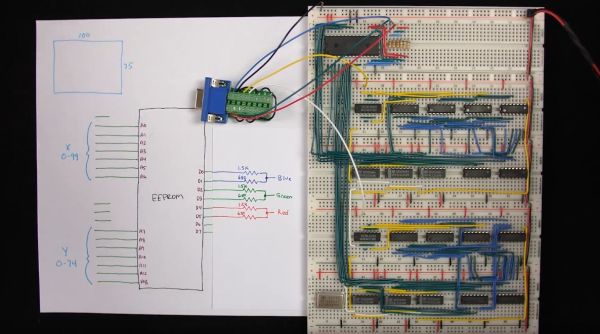
[Ben Eater] is back with the second part of his video series on building a simple video card that can output 200×600 pixels to a display with nothing but a VGA connection, a handful of 74-logic chips and a 10 MHz crystal. In this installment we see how he uses nothing but an EEPROM and a handful of resistors to get an image onto the screen.

The interesting part is in how the image data is encoded into the EEPROM, since it has to be addressable by the same timing circuit as what is being used for the horizontal and vertical timing. By selecting the relevant inputs that’d make a valid address, and by doubling the size of each pixel a few times, a 100 x 75 pixel image can be encoded into the EEPROM and directly addressed using this timing circuit.

The output from the EEPROM itself not fed directly into the monitor, as the VGA interface expects a 0 V to 0.7 V signal on each RGB pin, indicating the brightness. To get more than three colors out of this setup, [Ben] builds up a simple 2-bit DAC that allows for two bits per channel, meaning four brightness levels per color channel or 64 colors effectively.

See the video after the link for the full details. While pretty close to perfect, a small issue remains at the end in the forms of black vertical lines. These are caused by a timing issue in the circuit, with comments on the YouTube video suggesting various other potential fixes. Have you breadboarded your own version yet to debug this issue before [Ben]’s next video comes out?
Continue reading “Pushing Pixels To A Display With VGA Without A PC”

This 6502 Made From 74-Series Logic Can Run At 20 MHz

If you always wished you could get closer to the hardware with the 6502 in your classic microcomputer you’re in luck, because [Drass] has created a beautiful implementation of a 6502 using TTL logic chips. What makes it special is that it sits on a very neat set of PCBs, and due to its use of 74AC series logic it can run at much higher speeds than the original. A 20 MHz 6502 would have been revolutionary in the mid-1970s.

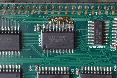
Neat reworking of what looks to be a reversed bus.

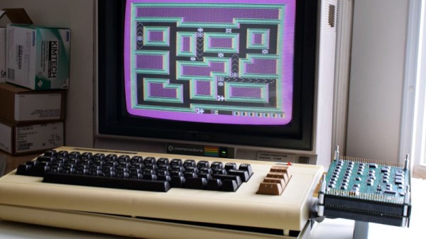
Through a flying ribbon cable, it can plug directly into the 6502 socket on classic microcomputers, and the website shows it running a variety of software on a Commodore VIC20. There is also a custom SBC as part of the suite, so no need for a classic micro if you want to put the CPU through its paces. The boards are not quite perfect, the website has a picture of some very neat reworking where it appears that a bus has been applied to a chip in reverse, but it certainly has the feel of a professional design about it.

This is a very tidy 6502, but it’s not the first we’ve seen and neither is it the most dis-integrated. There is a fascinating world of 74 logic CPUs to be explored, so it’s difficult to pick only one other to show you.

Thanks [Jeff] for the tip.

Behind The Pin: Logic Level Outputs

There is one thing that unites almost every computer and logic circuit commonly used in the hardware hacking and experimentation arena. No matter what its age, speed, or internal configuration, electronics speak to the world through logic level I/O. A single conductor which is switched between voltage levels to denote a logic 1 or logic zero. This is an interface standard that has survived the decades from the earliest integrated circuit logic output of the 1960s to the latest microcontroller GPIO in 2018.

The effect of this tried and true arrangement is that we can take a 7400 series I/O port on an 8-bit microcomputer from the 1970s and know with absolute confidence that it will interface without too much drama to a modern single-board computer GPIO. When you think about it, this is rather amazing.

It’s tempting to think then that all logic level outputs are the same, right? And of course they are from a certain viewpoint. Sure, you may need to account for level shifting between for example 5V and 3.3V families but otherwise just plug, and go, right? Of course, the real answer isn’t quite that simple. There are subtle electrical differences between the properties of I/O lines of different logic and microcontroller families. In most cases these will never be a problem at all, but can rear their heads as edge cases which the would-be experimenter needs to know something about.

Continue reading “Behind The Pin: Logic Level Outputs”

DDL-4 Is A Visually Pleasing Modular CPU

Today’s CPUs are so advanced that they might as well be indistinguishable from magic, right? Wrong! Fundamentally, modern CPUs can be understood logically like any other technology, it’s just that they’re very fast, very small, and very complex, which makes it hard to get to grips with their inner workings. We’ve come a long way from the dawn of the home computer in the 80s, but what if there was something even simpler again, built in such a way as to be easily understandable? Enter the DDL-4-CPU, courtesy of [Dave’s Dev Lab].

The DDL-4 is a project to build a modular 4-bit CPU using bitslice methods. This is where computations are broken down into simple operations with two-bit inputs, which are executed with basic logic gates like NOR and XOR. This is great for building a CPU from individual parts, as logic chips are readily available and their operation is readily understood. That’s what’s used here – good old 74-series logic, which you can find just about anywhere!

The build consists of a series of modules, each on its own colourful PCB and labeled on the silkscreen. These modules can then be configured and plugged together with edge connectors to build the CPU. The work builds upon [Dave]’s earlier work on the Mega-One-8-One, a recreation of the 74181 Arithmetic Logic Unit for educational purposes.

If you’re learning about computing in a bare-metal sense, projects like these that create CPUs from the ground up are a great way to get to grips with the basic concepts of computation. Once you’ve tried this, you could always graduate to building a 6502 in Minecraft.