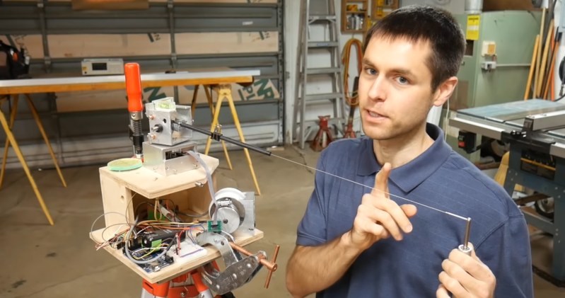
[Scott Rumschlag] wanted a way to precisely map interior spaces for remodeling projects, but did not want to deal with the massive datasets created by optical 3D scanning, and found the precision of the cost-effective optical tools lacking. Instead, he built a 3D cable measuring device that can be used to map by using a manual probe attached to a cable.
The cable is wound on a retractable spool, and passes over a pulley and through a carbon fiber tube mounted on a two-axis gimbal. There are a few commercial machines that use this mechanical approach, but [Scott] decided to build one himself after seeing the prices. The angle of rotation of each axis of the gimbal and the length of extended cable is measured with encoders, and in theory the relative coordinates of the probe can be calculated with simple geometry. However, for the level of precision [Scott] wanted, the devil is in the details. To determine the position of a point within 0.5 mm at a distance of 3 m, an angular resolution of less than 0.001° is required on the encoders. Mechanical encoders could add unnecessary drag, and magnetic encoders are not perfectly linear, so optical encoders were used. Many other factors can also introduce errors, like stretch and droop in the cable, stickiness of the bearings, perpendicularity of the gimbals axis and even the spring force created by the encoder wires. Each of these errors had to accounted for in the calculations. At first, [Scott] was using an Arduino Mega for the geometry calculations, but moved it to his laptop after he discovered the floating point precision of the Mega was not good.
[Scott] spend around 500 hours building and tuning the device, but the end result is really impressive. There are surprisingly few optical machines that can achieve this level of precision and accuracy, and they can be affected by factors like the reflectivity of an object.
If you do want to get into real 3D scanning, definitely take the time to read [Donal Papp]’s excellent guide to the practical aspects of the various technologies. Most of us already have a 3D scanner in our pocket in the form of a smartphone, which can be used for photogrammetry.


Very cool idea & execution
Shouldn’t he be sued for copying another companies product?
Not unless he’s selling it.
Nope. Anyone can make anything they want.
(If he were selling it, maybe, but that depends on what they’ve claimed in patents, and IANAL.)
No, Elliot, anyone cannot make anything they want:
“[…] whoever without authority makes, uses, offers to sell, or sells any patented invention, within the United States or imports into the United States any patented invention during the term of the patent therefor, infringes the patent.”
Make, use, offer, or sell. It’s all possible infringement.
Practically though, someone has to care enough to litigate…
There is also the concept of fair use.
@Tien How
Fair use is not related to patents.
Typically the make and use infringement factors are important when it’s at a commercial scale, like a factory copies a machine to make something, typically to avoid paying the patent holder. The public usually only observes this as related to the sale of copyright infringing items by unlicensed third parties.
There is also the issue that patents expire after a time, and without doing a patent search you do not know if you are trying to sell something that violates a patent.
Prodim proliner people told me a year ago that they have the patent and was just expired.
Interesting build and great description on its construction, and one approach to 3D space digitisation.
I think I’d ditch the cable and use fine Kevlar thread which weighs practically nothing, to reduce the droop. And instead of a single point origin, have three drum encoders at the corners of a triangle with the threads emanating from each tied to the stylus point so you do triangulation.
The drum retract spring tension might be kept uniform by a stepper motor that unwinds it a bit as the thread is extended, so the spring effectively becomes just a mechanical buffer to the stepper’s applied torque, with it controlled by say an Arduino which is given the data from the encoder’s knowledge of the distance unravelled.
So it’d be a bit like the digitisers from long ago that had pulleys and wires at each vertex leading to a bar the inside a cube frame, but turned inside out.
Kevlar strings are too springy to be used (between 1/2 and 1/3 of steel young modulus) and are subject to wear and tear.
Consider UHMWPE or Spectra, Dyneema, etc fishing line. High strength and low stretch. Vextran is lowest stretch and creep.
I would paint rings on the cable every mm and read their position as the cable rolls out with an optical encoder
Have a close look at the plywood moving @ 02:50 That will throw off his measurement quite a bit.
He talks about such errors further in the video :)
Great project! Must’ve been very satisfying when the spindle that rolls up the wire finally worked, looks super neat! I’ve been looking for something like this that can just take measurements in 3d space. Would be great if it had 2 origins, so 2 devices like this that measure each others position, then the object of interest so that you have a front and side measurement unreachable by one or the other device. One stick, two wires attached to it.
Would be great to see more detailed videos how it was made, considerations etc!
Or you can set up fiducial markers like surveyors — as long as you can reach 3 of them, you can measure your relative position even after you move your instrument. That way if you set up a series of say 8 or 10 fiducial markers in your space, and then you can measure something a lot larger than the device can handle.
I always chuckle when someone uses “low cost” and “I spent 500 hours on it” in the same paragraph.
Mostly, because I know I’ve said things like this way too many times myself.
Yeah. Time and money are finite, but interchangeable at some (flexible) rate. I call it $10/hr. 1000 hours of discretionary time vs. $10,000 of discretionary money, annually. If I am faced with spending 500 hours on something, I better be getting $5000 of value out of it. Otherwise it’s a waste of my time and I’m better off buying the solution.
Note that “value” bought by the expenditure of time includes both ‘experience’ and ‘fun’ (and ‘social capital’ and ‘youtube subs’ for the cynics…), so that factors in.
As someone who is currently trading their free time for money, I can say that THE most important thing about working on your project instead of buying it, is that it’s YOUR project you are working on, not someone else’s. This makes a huge difference and this is where fun and motivation comes from. Also you need free time. You can spend it on lying in bed or making something for yourself, but you need time to do something for yourself instead of earning money by using it for someone else.
Very low cost compared to the very over priced similar systems out there. I.e. Robotic Total Stations also.
Unfortunately I tend to be not payed for things I do at home, and since my work contract is on a day basis, my overtime is not paid anyway…
This is exactly the same idea as the good old Gametrak motion game controller used. Spool of string and a two axis joystick – two angles + distance.
Of course, the accuracy of the Gametrak is not comparable to this.
Stop blaming the HW. The ATmegas have no FPU, so any flop is pure SW using integers, anyways. Hence, any imprecision is caused by the compiler/SW in use, not the HW. You can always do 128-bit flops in SW if you want to. He might be limited by the available processing power at some point, but that was not the explanation.
True. Maybe you can collaborate with him and help upgrade the Arduino code to 64-bit or 128-bit arithmetic and see if the poor little hamster can turn the cage fast enough. My guess is that it might be doable since I am guessing he counts the encoder counts, and then converts them after he clicks the button to take a measurement. That said, you still need a big enough bucket, and I wonder if the whole RT processing loop can keep up with the data coming in.
Personally I would love to get the details on the encoders and the rest of the system. I can see myself building one of these ;-) I would have to consider if I have enough work for it to justify $500, but it is believable I might have one.
BTW, the suggestion of comparing this to a robotic total station is funny — last I looked a good one could only do a couple of mm accuracy at best, but can work to take measurements 100’s of feet away. That was also a $50,000 machine. So, this device is between 5x and 10x more precise than a total station and only works for a couple of meter volume, and cost $400 and 500 hours of time. Not only that, but if it breaks YOU CAN FIX IT! I call that all a win!
Also, if you can borrow a friends 3D printer or CNC router for a little bit, you might be able to automate collecting a LOT of data, and then use it to estimate where the error is coming from, and possibly how much. Yea I know you would have to consider vibration and heat, and …
Great work! Digital tech providing extreme precision to an old ideia (Albrecht Dürer engraving: Man drawing a lute – 16 century).
Mechanical LIDAR, I love it!
Nice idea, I’d do it a little differently.
All string measurements would be vertical or nearly so, base unit moves to place itself under string.
Think Roomba-type crawling robot.
You’d still encode string angles, of course!
The end of the string could be a fob of some sort that the robot seeks to stay under.
IR emitter in fob, seeker on base?
This should reduce string droop and the need for high tension; compensate mainly for the known elasticity of the string.
Base unit uses ‘optical mouse’ tech to determine movement/position on the floor; sub-millimeter direct reading, able to ‘read’ features on the floor as reference markers and find its way back to origin!
Inclinometers in the base unit could read floor slope; slanting or irregular surfaces could be recorded in 3d.
Start base unit at some arbitrary spot, sensors keep track of floor geometry, string keeps track of [hypotenuse] height above the floor.
The thing would follow you when you get near the end of the string!
I like moving toys…
Looks great!
When a ordered a new kitchen, the company first came with a large laserscanner to map the room with extreme detail.
Wonder why he did not take that route.