As we’ve followed a trail through Hi-Fi and audio systems from the listener’s ear towards the music source, we’ve reached the amplifier. In our previous article we gave a first introduction to distortion and how some amplifier characteristics can influence it, and here we’ll continue along that path and look at the amplifier itself. What types of audio amplifier circuits will you encounter, and what are their relative merits and disadvantages?
A Few Amplifier Basics
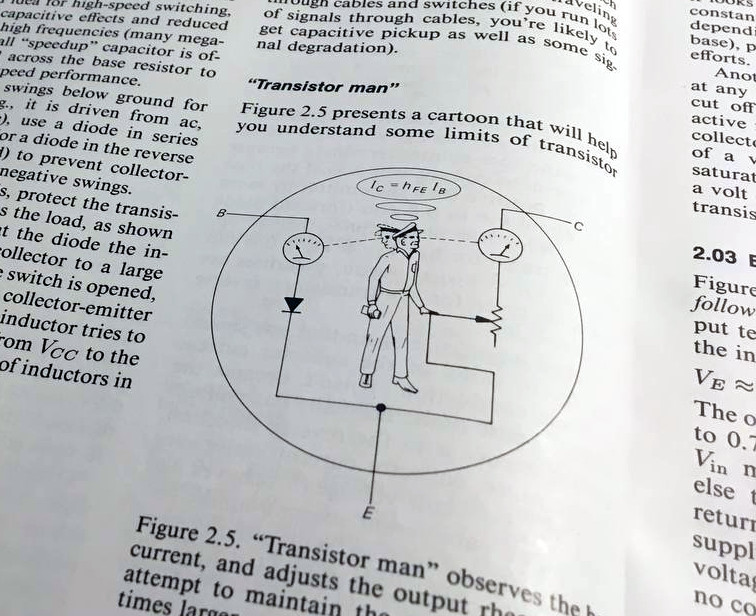
If you know anything about a transistor, it’s probably that it’s a three terminal device whose output pin forms part of a potential divider whose state is dependent on what is presented to its input pin. The Art of Electronics had it as a cartoon of a man standing inside a bipolar transistor and adjusting a variable resistor between collector and emitter while watching an ammeter on the base.
Properly biased in its conducting range, a transistor can behave as a linear device, in which the potential divider voltage moves in response to the input in a linear relationship, and thus the voltage on the output is an amplified version of the voltage on the output. This is the simplest of transistor amplifiers, and because different types of amplifier are referred to by lettered classes, it’s known as a class A amplifier.
The class A amplifier’s linearity makes it a good choice for the audio designer seeking low distortion, but it comes with a disadvantage. The potential divider action means that it is always passing current whatever state it may be in, thus the transistor must always be able to dissipate that power as heat. This gives the class A amplifier significant inefficiency, and thus one that is powerful enough to drive a loudspeaker must also emit the same power it delivers to the speaker, but as heat. Thus class A power amplifiers require extra cooling lest they get uncomfortably hot, and consume unnecessary power. There are class A audio power amplifiers on the market, but they remain unusual.
Having Your Cake And Eating It: The Class AB
The class A’s inefficiency comes from its transistors conducting continuously, it’s quite possible to reduce the bias to the point at which the transistors are in the off position but conduct only when a signal appears and pushes them in to conduction. This type of amplifier is referred to as a class B amplifier, and it typically only amplifies a portion of the incoming waveform. It solves the class A’s inefficiency but introduces a significant distortion to its output, which is why you will not encounter it in a simple form as an audio amplifier except perhaps in some very early tube radios.
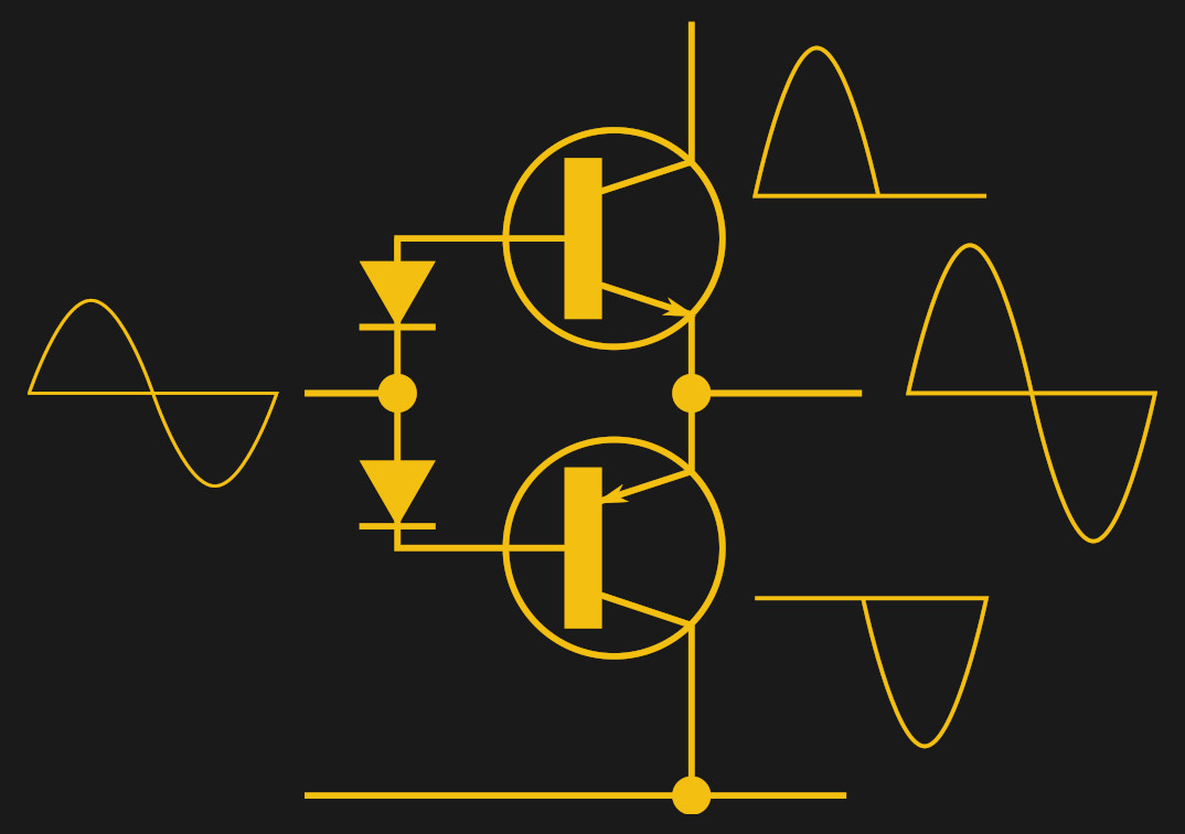
Given that a class B circuit can amplify half of the waveform cycle without distortion, an obvious progression is to combine two of them; one to amplify the upper half of the cycle and another the lower half.The idea is that the complete amplified waveform can be reconstructed from the two amplifiers, and yield a low-distortion and efficient result.
This works to an extent, but such a circuit still retains some distortion because the point at which the two waveforms meet is almost impossible to achieve without some kind of break, and this little glitch is known as crossover distortion. The solution to this problem comes in clever biasing, that operates the transistors in class B over almost all of their range but gives them enough bias to work in class A over its midpoint at which the two halves of the amplifier hand over from one to the other. This arrangement is referred to as a class AB amplifier, it delivers very low distortion alongside the all-important power efficiency, and forms the vast majority of analogue Hi-Fi amplifiers.
You might expect us to now move to the next letter of the alphabet and describe the class C amplifier here, but instead the final audio configuration is a class D amplifier. (Class C amplifiers are on-off squarewave amplifiers that have high efficiency but huge distortion. They’re no good for audio but find a use in RF power amplifiers, where LC circuits filter out the resulting harmonics.)
A Fully Digital Audio Amplifier: Class D
Most Hackaday readers will be familiar with the idea of pulse width modulation, the act of varying the energy delivered to a load by sending it pulses with a variable ratio of on-time to off-time. This is how many microcontrollers produce a pseudo analogue output for linear control of LED brightness or motor speed, to name but two examples. Given a high enough switching frequency PWM can be used to encode rapidly-changing analogue signals such as audio, and thus a PWM stream can be fed to a high power buffer to produce an audio output.
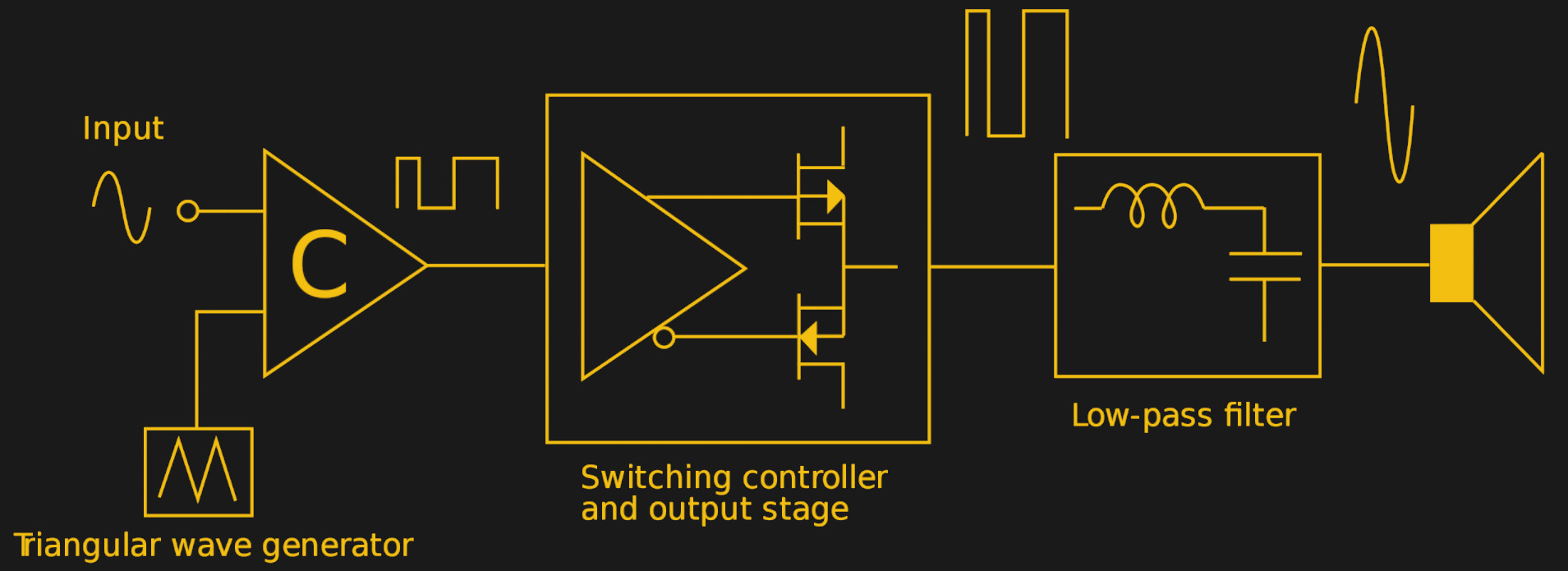
A practical class D amplifier uses PWM in this way, with its output transistors simply working a high-speed switches. There’s a passing similarity to a class C amplifier, but the difference is that the class D switches at many times the signal frequency while the class C operates at its signal frequency. The class D amplifier produces a high-power PWM pulse train, which is converted into high-power audio to drive a speaker by means of a low-pass filter network. The advantage of a class D amplifier is that it can deliver extreme efficiency, meaning that it can be built smaller and lighter than a linear circuit and with less need for heat management.
There are a few further classes of amplifier which are worth mentioning, classes E and F which are more RF amplifiers that rely on pulsing resonant LC networks with short pulses to derive an output, and classes G and H which are variations on a class AB amplifier with a PSU that varies to minimise standing current. You may encounter ICs that offer classes G and H, but from an audio point of view they can be considered as simply more efficient versions of a class AB amplifier.
We’ve taken a look at the circuit topologies behind the amplifiers you will find in your Hi-Fi system, and also in every audio-producing device you own. So then, the question is: which is better, class A, class AB, or class D? The answer to that isn’t cut-and dried, as the performance of an amplifier depends not necessarily on its principle but upon how its designer has executed it. It’s possible to make audio amplifiers in all of the above topologies that are either truly awful or exquisite-sounding, so perhaps it’s best not to get too hung up on it. A class A amplifier gives you bragging rights and keeps your house warm, a class AB amplifier is what you’ll find in most Hi-Fi separates, and a class D amplifier will be lighter and cooler. Amplifiers: there, we fixed it!


I’m just wondering if anyone could explain how to calculate output impedance for a class AB amplifier, or link to a good explanation understandable to the level of people reading this article. Also , maybe a practical way to measure output impedance. Thanks
I haven’t set out to do the math, but my gut tells me that because any class AB you encounter in the wild will be feedback regulated, the output impedance you could measure under rated loads will be effectively 0.
As for testing it, that should be a simple matter of measuring the open circuit voltage and then introducing a known load and measuring the loaded voltage, extend as necessary into reactive components if you’re interested in the complex impedance.
My first thought is, “Why do you want to do this?”
The output impedance of modern transistor amplifiers is quite low, generally below an ohm.
It is not necessary to match input and output impedance. But you want your output impedance to be the same as, OR lower than the speaker impedance.
When impedance is matched, maximum transfer of power is accomplished. So, that’s good for efficiency.
Anything lower than matched impedance doesn’t really lose power transfer. But it exerts tighter control of the speaker cone.
Think of the “impedance” of the power line coming into your house. It typically must supply 200 amps at just about the same voltage as it supplies one amp! This is a very low impedance! Because of this, you can turn things off and on with little noticeable effect on the operation of other things that are on.
Same applies to sound systems with more than one set of speakers. My amplifier has terminals for two pair of speakers, and either, both, or none can be switched on. When you go from one pair to two, the volume of the first pair does not go down.
If the amplifier had an 8Ω impedance, switching a second pair of 8Ω speakers on would reduce the volume of the first pair of speakers by 6db, which is fairly noticeable. But that doesn’t happen, because the amplifier’s output impedance is probably on the order of hundreds of milliohms.
(Now, you couldn’t actually drive a hundred milliohm speaker with the amp, because then, output power dissipation from suppling too much current becomes the limiting factor.)
You mention “calculate” and “measure,” as though they were the same thing.
Calculating the output impedance is possible, by using the spec sheet for the amplifier’s output transistors, and dividing the delta voltage by the delta current in the transistor’s active operating region. But again, that won’t tell you how much current you can get out of the amplifier.
Measuring the output impedance is tricker, but doable. With a small enough signal so that you don’t blow the amp by going over the all-important current rating of the output transistors, put various fixed resistors across the output, and measure the voltage. You should see TINY reductions in voltage as you reduce the resistance of the load. You can calculate the power transfer of each resistor, using P = E2/R. One of those measurements will be a peak. That’s your output impedance.
But really, except as an exercise, it doesn’t matter any more than the impedance of your home electrical feed. You don’t want the brightness of one lamp going down by 50% when a second lamp is turned on, which is what would happen if your electrical feed impedance were matched to the load impedance.
No
Assume the open-circuit output voltage of the amplifier is 1 Vrms. Loaded with 8Ω speaker, the voltage across the speaker is 1/2 Vrms. Loaded with 2 parallel 8Ω speakers, the voltage across the speakers is 1/3 Vrms. (1/3)/(1/2) = 2/3, about -3.52 dB. The same result is achieved if the speakers are wired in series.
“When impedance is matched, maximum transfer of power is accomplished. So, that’s good for efficiency.”
Not exactly. When impedance is matched THE SAME AMOUNT OF POWER IS DISSIPATED IN THE SOURCE AS SHOWS UP IN THE LOAD. Which is why electrical power transmission networks are always VERY FAR from being matched. If it were, the alternators would go up in flames.
Impedance matching is important for vacuum tube amps which have output transformers because the tube plates need to operate into a pretty narrow range of impedance for linearity and efficiency, and the speaker impedance, reflected back through the output transformer, comprises that load. With solid state amps, the load impedance determines the maximum power that can be delivered (because it’s V^2/R and V is fixed), but that’s about the only reason it matters.
Having the amplifier (and cable) impedance low enough is important to reduce the overshoot in the speaker cone. When voltage is applied to the speaker coil, it gets the diaphragm moving. But what stops it? Either slow dissipation through mechanical losses, or fast dissipation due to back-EMF in the coil.
The ratio of the speaker to amplifier impedance is called “amplifier damping factor” and if it gets too low, the frequency response gets quite uneven.
I would guess that the cable impedance is high, maybe around 100-200 ohms, but its resistance is low.
A transmission line’s (a “cable” sometimes) impedance doesn’t matter until the line is a significant part of a wavelength in length — thousands of meters at 20kHz. Further, at audio frequencies, a line’s impedance is not constant (i.e. it doesn’t have a “characteristic impedance”), but rather is a function of the actual frequency.
“When impedance is matched, maximum transfer of power is accomplished. So, that’s good for efficiency.”
I don’t think so. When impedance is matched, the maximum power is available (or taken out of the amplifier). However, the efficiency is <= 50%. If the load impedance is higher than the source impedance, the efficiency increases above the 50% with higher load impedance. Don't mix 'maximum power' with 'maximum efficiency'.
Thanks for the reply. Why do I want to know the impedance?
Maybe wrongly (???) I wanted to know impedance because I was thinking of making an AB amp to drive a home made ribbon speaker which will have a quite low impedance.
To measure output impedance – place a dummy load (of suitable power) like a shunt resistor in series with the speaker. Apply a sine input and measure voltages across speaker and series resistor and calculate as a resistive divider.
Some problems with this method –
1) it measures at only the applied input frequency as output impedance changes with frequency.
2) Similarly the impedance of the speaker changes with frequency.
In any case it will be a very low output impedance.
Some notes:
The class AB diagram above shows and input and an output. We assume the output goes to the speaker and this is correct.
We also assume the input is the signal source or perhaps the signal source after a pre-amp. This is not correct in a common consumer class AB amplifier.
In a common class AB the input to the power stage is actually the difference between the output and the signal source. This provides better signal reproduction by eliminating some of the non-linearity in the output stage and pre-amp stage.
This however comes at a cost. One of these costs is the risk of oscillation so the output of the difference amp (and input to the class AB power stage) is damped to prevent oscillation. This causes phase differences at different frequencies and also difference in output impedances at different frequencies. These are very minor but may need to be considered.
Also (somewhat related). The class AB diagram shows the use of two diodes for bias. This is a rough way of doing this that you van use in lo-fi situations like driving a 1-2 Watt sleeker from a micro-controller. It “kind of” works because the voltage drop across a forward biased silicon diode is about the same as the Vbe voltage drop across the base and emitter of a silicon transistor. I say “kind of” because there are variations resulting from manufacturing processes and even temperature. This is usually solved by placing emitter resistors on the transistors in lo-fi amps.
However in a quality amp the bias current is set by a floating constant current source-sink between the bases of the transistors.
The best-known output circuit of a hifi bipolar amp uses emitter followers with resistive degeneration, as you stated. The bases of the output transistors are separated by the voltage created across a circuit known as a Vbe multiplier, which voltage is made proportional to the temperature of the output transistors by thermally coupling the Vbe multiplier transistor to the output transistor. (See the wikipedia entry for “rubber diode” for a typical circuit.) A capacitor across the Vbe multiplier improves high frequency performance.
Correction: not proportional, rather inversely proportional. That’s an approximation.
You can run Spice to simulate the actual analog circuit. It is a lot easier than trying to calculate that manually. The results are only as good as the simulation models.
Don’t forget about class AA amplifiers. Technics did some hackery there!
That’s just a marketing term. It’s actually an AB amp with slightly modified biasing so the inactive leg never completely shuts off.
I thought the “AA amplifiers” were an optimization of a twelve-step program? :-)
AA is certainly a thing. Not efficient mind. The purpose is to cancel distortion generated in the gain stages and potentially double current output over a single/normal class A amp. Cant find example, but have tripped over a commercial amp that did this. Not modern – a retro thing. Cant imagine it being done anymore.
The only other thing I can find is an amp that uses a class A stage as a feedback amplifier to drive a class B amp past the crossover point, so it’s not AB but A+B
Then there’s various other weird amps which have a class A output stage but vary the voltage applied to reduce the idling current. But these are called something like A+
Here’s a nifty little idea. Put a high gain pre-amp stage ahead of the driver and throw some negative feed-back from the PA stage output right back to the input of the pre-amp. I hope you all know what “Gain band-with product” is but including the PA stage in the feedback look drops the output impedance, improves linearity, increases the bandwidth and increases the “Damping Factor”. I think Renkus Heinz did it and maybe even celestion. I made one for myself about 15 years ago to create a faithful oscilloscope pattern projecting a laser onto a wall using high power servo coils. I never published anything as it was just me tinkering.
Encompassing any form of driver stage in a feedback loop forces linearity, lowers output impedance and increases bandwidth.
If you want to mess with class-d amps on the cheap you can make a (bad) one with an arduino: set up the adc for free running, triggering an interrupt on each conversion, and have your ISR move the ADC value into the PWM top register with the PWM output set up to connect to two pins, one inverted, to drive a push-pull to the speaker. The output is clearly audible and voice is recognizeable, and since the entire program save for the ISR is running in hardware you have the full resources of the arduino to do any audio effects you’d like.
A good use case for a 555.
FYI: https://www.electrobob.com/555-class-d-amplifier/
High frequency + high current + audio circuits would benefit from using a PCB instead of messy wired breadboard.
Just a small remark:
“A Fully Digital Audio Amplifier: Class D”
The “D” in “Class D” does not stand for “digital”, it just happened to be the next letter at the time. Class D is not necessarily digital! PWM can be (and was) implemented completely analog. It is a switching amplifier. Sure, the principle is implemented digitally nowadays – but that was not always the case.
+1
A now classic project is to implement a class D amplifier with 555s and see if you can make it work.
A 555 has an analog input and a digital output.
Elementary Electronics, about 1974, build a class d amp with a 555. Not much power, but it gives the rudiments.
I think the first hobby article was in Wireless World, but about 1964, Jim Kyle had an article in 73, all transistors.
Of course class D is digital. It goes between high and low, and hopefully as short a transition time as possible. The fact that transistors werre used in early examples doesn’t make it any less digital.
It absolutely is not digital. It may have 2 discrete output voltages (prior to the LPF), but these are not discrete time devices, when the switching occurs is completely analog. The D is not for digital.
All this talk of amplifier output impedance really misses the mark. Primarily, the notion that a low output impedance is what’s actually desirable. (Also, a common misconception that output impedance is effectively an actual impedance in the output of the amplifier.)
Partly inspired by something I saw while repairing a solid state guitar amplifier that was designed to sound like a tube amp, further inspired by a two part article on EE Times (that was companion to a book published on the subject, circa 2013), some years ago I went down the path of current mode audio amplifiers. It’s something that I’d wondered about for years, and I wish I’d done it earlier.
My experience with it has been that it has way more effect on sound quality than the topology of the amplifier. The topology of the amplifier, provided that it’s not a crappy design, is primarily affecting efficiency, not sound quality.
I’ve since been modifying amplifiers, usually class ABs (because the circuit is easier to modify), to be ‘transconductance’, or current mode amplifiers. It has been like going from tape cassette to CD all over again. And as for my amplifier output impedance… it’s gone tremendously high. Probably in the range of kilo-ohms.
In other research I’ve done about this subject, my current theory is that the benefits have to do with counteracting phenomena in the speaker that cause distortion; primarily back EMF from the motion of the cone. That back EMF, when the speaker is coupled to a voltage mode amplifier, sums with the intended signal being put in to the speaker. I also believe that this is the predominant factor in the sound of an older style vacuum tube amplifier. The tube-fags I’ve run across were on to something, most just didn’t understand what the mechanism improving the sound actually was.
If you experiment with this for yourself, you’ll need to pay attention to passive crossovers, specifically padding (usually of tweeters). Typical circuits are designed for voltage mode operation and the padding does not function for current mode operation.
Typo – “… thus the voltage on the output is an amplified version of the voltage on the output.”
I believe you mean to say that the voltage on the output is an amplified version of the voltage on the input.