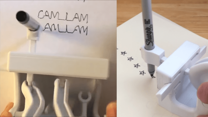
3D printers are great at creating complex geometry out of plastic, and that geometry can often pull off some impressive tricks. [DaveMakesStuff] found a way to generate geometry that draws 2D shapes with a pen and some fancy cams, and it’s really fun to watch.
The build is relatively simple. It consists of a frame which holds a 3D-printed cam turned by a hand crank. That cam controls the movement of a pen in two dimensions, letting it draw all manner of shapes. Videos on Reddit demonstrate it drawing squares, figure eights, and stars, while on YouTube, it writes the phrase “CAM I AM.”
According to [DaveMakesStuff], he figured out how to create the cams with “hours and hours of tedious CAD work.” We imagine there’s a way to do this with maths instead in parametric modelling software, and await such a build on the Hackaday tipsline. Those eager to recreate the build can explore the files on Thingiverse.
We’ve seen some great 3D-printed mechanisms before, too, like this zig-zag cam for a sewing machine. Video after the break.
[Thanks to JohnU for the tip!]


I’m legitimately excited for someone to figure out the math behind generating these cam wheels for arbitrary lines
Whereas I’m genuinely excited.
I’m authentically excited.
I’m absolutely excited
I am logically excited
I’m certifiably excited
Fourier analysis, was worked out a long time ago to render high quality characters on analogue cathode ray tube displays. https://www.youtube.com/watch?v=-qgreAUpPwM
I <3 this!
Yes, 1 is [less than] 3!
This is the basis of the old “automata” that could reproduce complicated sketches, as in the movie Hugo.
Here’s a slightly more modern version, IIRC it can be programmed with an arbitrary phrase, it just changes the camming. $365k.
https://www.jaquet-droz.com/sites/default/files//videos/pieces/Jaquet-Droz_J899-000-064_Signing-Machine_1080p.mp4
and an article: https://quillandpad.com/2018/05/20/jaquet-droz-signing-machine-keeping-handwriting-alive-with-a-machine/
Just what you need the next time you buy a house, and have endless forms to sign…
Signature writing machines have been around for many decades now. Reading this article, I’m 47% curious as to how these actually work.
For every angle of the cam, one axis is the distance between the point on the cam and the plane of the handcrank, while the other axis is the radius of the cam.
I think the hardest part is not to convert the parametric curve to an appropriated cam, but to convert the shape you want to draw into a parametric representation.
For every (x,y,t) point in cartesian coordinates on the drawing (with t being time because you may go multiple times over the same point), it corresponds to a (r,theta,z) point in cylindrical coordinates on the cam (because the cam is 3D). You have r=y and z=x (depending on where you see the axis that can be reversed).
Finally, theta = constant * t To calculate the constant, you have to set the time T that the drawing will take, and you have 360° (or 2pi radians -_-) = T.
After tracing the corresponding line of points of contact of the cam, you do a sweep extrusion of a profile of your choice, and then you don’t forget the connecting disk/flat potato between the cam and its axis.
The limitations will come from the lack of motion reduction : The cam can’t be smaller than the drawing, if you wanna do it in one go. Moreover, friction, contact point size and printer resolution, limit the possible geometry.
You can probably lubricate the cam and diminish the point size, but if you diminish the point size too much it will be more fragile and dependent on the printer resolution , so the speed will be reduced.
Actually, it may be cooler than a stamp, but it’s no better than a stamp, except for signatures.
That was verbose, but I hope I’m understood, and also hope I’m not wrong.
I wrote it as an answer to 🔥 (@fire), but the website decided otherwise…
For the parametric curve you may start with a circle as baseline, and then add sine or cosine waves to it to forge the letter outlines (so from O to I add 2*f, from O to X add 4*f). It is basically a fourier transformation of the outer boundary of the letter, the holes are more tricky, if you want to describe these too. I know someone who did a character recognition with this method as master thesis, but sadly I’ve lost contact.
The mechanism may mechanically add these fourier coefficients and move to the next letter with a Geneva drive.
“2d printer”
looks like cursive to me
You aren’t obligated to approximate the shapes with a sum of sines : From memory, this is used to draw a shape using a gear train, because the contact points between the gears follow geometrically sums of sines and cosines. I think what this method is the most adapted for is for things like this :
https://www.myfourierepicycles.com/
It’s a far more complex way because of the number of parts used, the method using cams has the pro of being printable with only one complex 3D part, while the method above uses a great number of (simple ?) parts.
I found multiple papers relating to character recognition using fourier coefficients.
You are right, my brain got stuck at summing the coefficients to approximate a shape. It is easier to do this before printing the part. The nice thing with fourier coefficients is that you can calculate a typical set for each general shape you need, and adjust that by adding some more coefficients for fine tuning. I would think this turns out easier than tweaking x(t) and y(t) “from zero” for every shape, but maybe my brain is stuck again…
Is there like a generator somewhere to turn text into a cylinder for one of these?