Flip-Segment Digital Clock Is A Miniature Mechanical Marvel

Clocks are such mundane objects that it’s sometimes hard for them to grab your attention. They’re there when you need them, but they don’t exactly invite you to watch them work. Unless, of course, you build something like this mechanical flip-segment clock with a captivating exposed mechanism

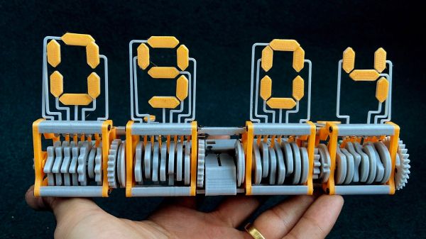
“Eptaora” is the name of this clock, according to its inventor [ekaggrat singh kalsi]. The goal here was to make a mechanical flip-segment display as small as possible, which meant starting with the smallest possible printable screw hole and scaling the design up from there. Each segment is controlled by a multi-lobed cam which bears on a spring-loaded cam follower. When the cam rotates against the follower, a segment is flipped up from the horizontal rest position to the vertical display position. A carryover mechanism connects two adjacent displays so that each pair of digits can be powered by a single stepper, and the finished clock is quite small — a little bit larger than the palm of a hand. The operation seems quite smooth, too, which is always a bonus with clocks such as these. Check out the mesmerizing mechanism in the video below.

We’d have sworn we covered a similar clock before — indeed [ekaggrat] says the inspiration for this clock came from one with a similar mechanism — but we couldn’t find it in the back catalog. Oh sure, there are flip-up digital clocks and all manner of mechanical seven-segment displays, but this one seems to be quite unique, and very pleasing.

Continue reading “Flip-Segment Digital Clock Is A Miniature Mechanical Marvel”

Hand-Cranked Doodler Made Using A 3D Printer

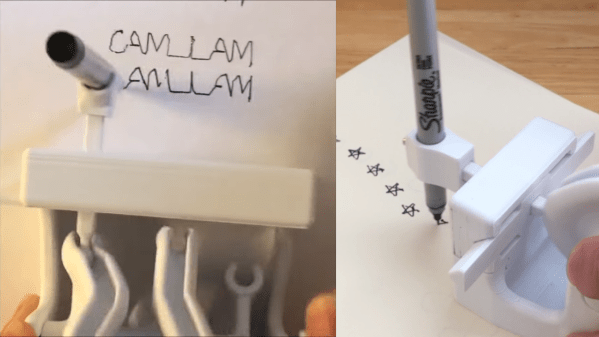
3D printers are great at creating complex geometry out of plastic, and that geometry can often pull off some impressive tricks. [DaveMakesStuff] found a way to generate geometry that draws 2D shapes with a pen and some fancy cams, and it’s really fun to watch.

The build is relatively simple. It consists of a frame which holds a 3D-printed cam turned by a hand crank. That cam controls the movement of a pen in two dimensions, letting it draw all manner of shapes. Videos on Reddit demonstrate it drawing squares, figure eights, and stars, while on YouTube, it writes the phrase “CAM I AM.”

According to [DaveMakesStuff], he figured out how to create the cams with “hours and hours of tedious CAD work.” We imagine there’s a way to do this with maths instead in parametric modelling software, and await such a build on the Hackaday tipsline. Those eager to recreate the build can explore the files on Thingiverse.

We’ve seen some great 3D-printed mechanisms before, too, like this zig-zag cam for a sewing machine. Video after the break.

Continue reading “Hand-Cranked Doodler Made Using A 3D Printer”

A Guide To Milling PCBs At Home

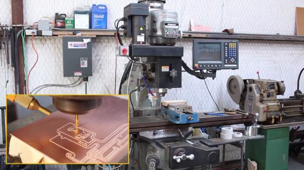
If you keep up with various retro vacuum tube projects, you probably have run across [UsagiElectric] aka [David]’s various PCBs that he makes on his own Bridgeport EZ-Track 3-axis milling machine — massively oversized for the job, as he puts it. In a recent video, [David] walks us through the steps of making a sample PCB, introducing the various tools and procedures of his workflow. He points out that these are the tools he uses, but the overall process should be similar no matter what tools you use.

  • Logisim to validate logic designs
  • TINA-TI, Texas Instrument’s version of the TINA SPICE simulator
  • DesignSpark PCB for schematic entry and PCB layout
  • FlatCAM, a computer-aided PCB manufacturing tool

For this video, [David] makes a half-adder circuit out of four vacuum tubes plus a seven-segment VFD tube to show the combined sum and carry outputs. Momentary switches are used to generate the two addends. Using this example, he proceeds to design, simulate, build and demonstrate a working circuit board. We like his use of the machined pin socket inserts for building a vacuum tube socket directly into the board.

Now this process isn’t for everyone. First of all, a Bridgeport mill is a pretty good sized, and heavy, tool. That said, these procedures should adapt well to other milling machines and engravers. We should point out that [David] is making boards mostly for vacuum tubes, where circuit trace width and spacing distances are generous. If you’re planning to make home PCBs for a 273-pin PGA chip, this isn’t the technique for you.

It seems that the bulk of [David]’s vacuum tube PCBs are single-sided, and reasonably so. They use wire links here and there to jump over traces. Adapting this process to double-sided PCBs is doable, but more complex. Are you milling double-sided boards in your lab? If so, let us know about it in the comments below.

Continue reading “A Guide To Milling PCBs At Home”

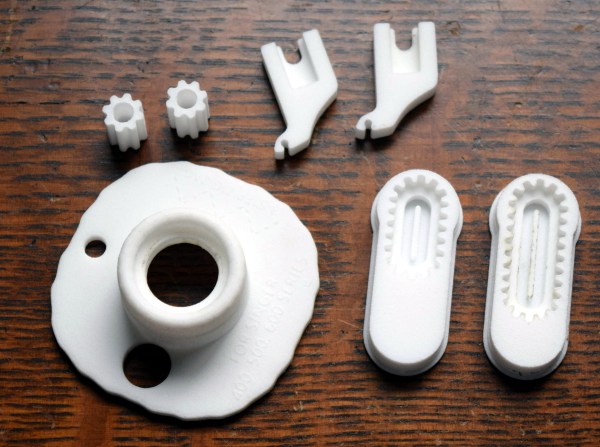
An array of 3D-printed parts for old sewing machines.

Printed Sewing Machine Parts Extend Singer’s Range

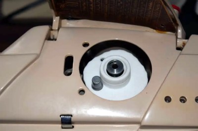
[Grow Your Own Clothes] had finally found their ideal sewing machine for doing zig-zag stitches (/\/\/\) and converting to a treadle drive (mechanically foot-fed) — a Singer 411G. This is a well-respected workhorse of a machine, and if you see one in a secondhand store, you might want to grab it. The only problem is that its multi-step zig-zag stitch is a 4-stepper and not a 3-step, which is what [GYOC] prefers. Having heard it was possible to hack them into doing a 3-step, [GYOC] set out to learn Tinkercad and grow their own sewing machine parts.

A 3D-printed cam lets this machine do the zig-zag in three steps instead of four.
The new zig-zag top hat cam in place.

So once upon a time, sewing machines didn’t just do a bunch of things out of the box. They needed an array of plastic cams to do different stitches, kind of like trading out the element or disk in a typewriter to print in italics. While most machines still have exchangeable feet for different needs and special parts for sewing things like buttonholes, most domestics now have decorative stitches and their cams built in.

The 3-step zig-zag cam was just the beginning. [GYOC] decided to make a few more parts before their Tinkercad knowledge faded: a needle adapter with an improved design, some tension stud sprockets for a different machine, and a couple of buttonhole templates for making different sizes with a buttonholer. Although they aren’t giving away the files for free, all of these parts are available quite cheaply in their Shapeways store.

Got an old machine you don’t know what to do with? Try converting it to a computerized embroidery machine.

Thanks for the tip, [Raphael]!

Mechanical 7-segment display

A One-Servo Mechanical Seven-Segment Display

The seven-segment display may be a bit prosaic after all these years, but that doesn’t mean there aren’t ways to spice it up. Coming up with a mechanical version of the typical photon-based display is a popular project, of which we’ve seen plenty of examples over the years. But this seven-segment display is quite a mechanical treat, and a unique way to flip through the digits.

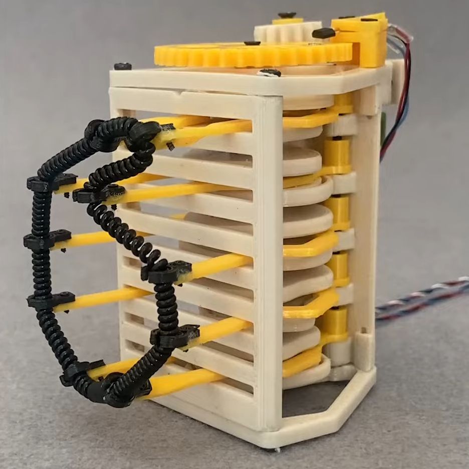
With most mechanical displays, we’re used to seeing the state of each segment changed with some kind of actuator, like a solenoid or servo. [Shinsaku Hiura] decided on a sleeker design using a 3D-printed barrel carrying one cam for each segment. Each hinged segment is attached to an arm that acts as a follower, riding on its cam and flipping on or off in a set pattern. Which digit is displayed depends on the position of the barrel, which is controlled with a single servo and a pair of gears. It trades mechanical complexity for electrical simplicity and overall elegance, and as you can see from the video below, it’s pretty snappy.

We think the best part of this build is figuring out the shape of the cams. We wonder how they compare to the cam profiles in [Greg Zumwalt]’s mechanical display; it uses two separate discs with grooves, but the principle is pretty much the same.

Continue reading “A One-Servo Mechanical Seven-Segment Display”

When The Right Tool Is Wrong

I’m a firm believer in using the right tool for the job. And one of the most fantastic things about open-source software tools is that nothing stops you from trying them all. For instance, I’ve been going back and forth between a couple, maybe three, CAD/CAM tools over the past few weeks. They each have their strengths and weaknesses, and so if I’m doing a simpler job, I use the simpler software, because it’s quicker and, well, simpler. But I’ve got to cut it out, at least for a while, and I’ll tell you why.

The first of the packages is FreeCAD, and it’s an extremely capable piece of CAD/CAM software. It can do everything, or so it seems. But it’s got a long shallow learning curve, and I’m only about halfway up. I’m at the stage where I should be hammering out simple “hello world” parts for practice. I say, I should be.

Fortunately/unfortunately, some Hackaday readers introduced me to KrabzCAM through the comments. It’s significantly less feature-full than FreeCAD, but it gets the job of turning your wife’s sketches of bunnies into Easter decorations done in a jiffy. For simple stuff like that, it’s a nice simple tool, and is the perfect fit for 2D CAM jobs. It’s got some other nice features, and it handles laser engraving nicely as well. And that’s the problem.

Doing the simple stuff with KrabzCAM means that when I do finally turn back to FreeCAD, I’m working on a more challenging project — using techniques that I’m not necessarily up to speed on. So I’ll put the time in, but find myself still stumbling over the introductory “hello world” stuff like navigation and project setup.

I know — #first-world-hacker-problems. “Poor Elliot has access to too many useful tools, with strengths that make them fit different jobs!” And honestly, I’m stoked to have so many good options — that wasn’t the case five years ago. But in this case, using the right tool for the job is wrong for me learning the other tool.

On reflection, this is related to the never-try-anything-new-because-your-current-tools-work-just-fine problem. And the solution to that one is to simply bite the bullet and stick it out with FreeCAD until I get proficient. But KrabzCAM works so well for those small 2D jobs…

A hacker’s life is hard.

Motorcycle Needs Custom Latching Switches For Turn Signals

While modern cars have been getting all kinds of fancy features like touch screens, Bluetooth, crumple zones, and steering wheel controls, plenty of motorcycles have remained firmly in the past. Some might have extra options like a fuel gauge or even ABS if you’re willing to spend extra, but a good percentage of them have the bare minimum equipment required by law. That equipment is outdated and ripe for some improvements too, like this ergonomic custom turn signal switch built with custom latching switches.

Since motorcycle turn signals don’t self-cancel like car signals the rider has to cancel it themselves, usually by pushing an inconveniently tiny button. This assembly consists of four separate switches, two of which control the left and right turn signals. Since both can’t be on at the same time, they include circuitry that can detect their position and a small motor that can physically de-latch them if the other one is pressed. The entire assembly is 3D printed, including the latching mechanism, and they are tied together with a small microcontroller for the controls.

The truly impressive part of this build is the miniaturization, since all four buttons have to be reached with the thumb without removing the hand from the handlebar. The tiny circuitry and mechanical cam for latching are impressive and worth watching the video for. And, if you need more ergonomic improvements for your motorcycle there are also some options for cruise control as well, another feature often lacking in motorcycles.

Continue reading “Motorcycle Needs Custom Latching Switches For Turn Signals”