Repairing electronic devices isn’t as hard as it used to be. Thanks to the internet, it’s easy to find datasheets and application notes for any standard component inside your gadget, and once you’ve found the faulty one, you simply buy a replacement from one of a million web shops — assuming you don’t end up with a fake, of course. When it comes to non-standard components, however, things get more difficult, as [dpeddi] found out when a friend asked him for help in repairing a Roland Juno-G synthesizer with a broken display.
The main issue here was the fact that the display in question was a custom design, with no replacement or documentation available. The only thing [dpeddi] could figure out from the service manual was the basic pinout, which showed a parallel interface with two lines labelled “chip select” — an indication that the display contained two separate controllers. But the exact protocol and data format was not documented, so [dpeddi] brought out his logic analyzer to try and decode the signals generated by the synthesizer.
After a bit of trial and error, he was able to figure out the protocol: it looked like the display contained two KS0713-type LCD controllers, each controlling one half of the screen. Finding a compatible replacement was still proving difficult, so [dpeddi] decided instead to decode the original signals using a microcontroller and show the picture on a modern LCD driven by SPI. After some intial experiments with an ESP32, it turned out that the task of reading two reasonably fast parallel buses and driving an even faster serial one was a bit too much for the ESP, so [dpeddi] upgraded to a Raspberry Pi Pico. This worked a treat, and thanks to a 3D-printed mounting bracket, the new display also fit snugly inside the Roland’s case.
The Pico’s code is available on [dpeddi]’s GitHub page, so if you’ve also got a dodgy display in your Juno-G you can simply download it and use it to plug in a brand-new display. However, the method of reverse-engineering an existing display protocol and translating it to that of a new one is pretty universal and should come in handy when working with any type of electronic device: say, a vintage calculator or multimeter, or even another synthesizer.


I have Juno-G but gladly the LCD was replaced already.
However the original (?) schematic look a lot like the “standard” 128×64 3D-printer display (SS-something driver). I don’t know if I got it right but maybe there is easier way to replace rather than using totally different standard display + raspberry pico ?
Why do something simple when you can do it complex as well and learn a ton in the process?
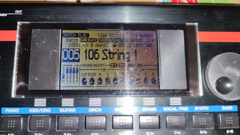
The original display was a 240×96 pixel with 2 chip select. Roland itself released new display revision for warranty that required a new firmware, but the price was expansive and now out of production. The original display was quite big about 150x60mm.. nowadays you can find 240×128 LCD and the price is higher than a TFT. And usually smaller then required.
Probably even with a LCD with the same size and characteristics wouldhave required a protocol converter.
Just a heads up, I posted a link to your website in a reddit thread earlier and just noticed it started returning a 502 since then.
Your work is important for preserving the Juno G and greatly appreciated! I hope it does not become one of the many lost sources of valuable information.
Will check later…
can you tell me where I can get that 3-D printed bracket to put a new display in?
Amazing that such old-timey circuitry would be too fast for an ESP32. Wouldn’t have expected that.
The keyboard CPU is a HD6417706F133 that is clocked at 133 MHz. Faster then the default clock of the ESP32. Originally I hope to use just a loop, then I thought to use irq to poll for display data, but the microcontroller interrupt speed was around 100/200khz, while the data frequency was around 7mhz. With the ESP32 using DMA I was able to get the half display working by using the one chip select line to clock the i2s circuit. So the answer is ESP32 could have worked using DMA but not in this situation because of the two CS lines.
The ESP32 have two I2S peripheral but the data sheet says that just one could be used in parallel mode at the same time…
Fast is relative. The old displays did so much in parallel and too many micros have slow I/O, even if you use inline code to speed it up.
It’s been a running thought for many of my long-term project ideas: e.g. making a parallel IDE hard-drive *controller* is relatively easy from any microcontrooler. But, making a parallel IDE hard disk “device,” that responds to a controller, is quite a bit more difficult because of the timings involved. Same goes for e.g. SRAM or EPROMs, or even HD44780 LCD displays.
The controlling processor expects a response within a handful of clock cycles (like two or three, if that). So even, say, an old 8051 which runs at 8MHz and yet only executes instructions at 1/12th of that, still expects its memory/IO devices to respond to a read request in only a few hundred nanoseconds. That’s easy enough to do with, say, a register like the 74LS374, as long as it’s already storing the data that the controller is requesting. And it would be equally easy to write to from the controller. But it’s way more difficult for a microcontroller to decode the address, then load the appropriate data from RAM to its GPIOs, during a read. Or decode the address, read its GPIOs, then store that in its RAM, before the next write comes through. It takes a lot of instructions, which can take a long time, even at 100+MIPS!
I’m not too familiar with DMA in microcontrollers, but most (if not all) uCs I’ve seen have “external memory interfaces” which are controller-side only. It’s not like the RAM inside the uC can be accessed through that bus. So, even DMA would be impossible for them.
I think most folk opt for an intermediate CPLD, dual-port RAM, a whole bunch of 74LS374’s, etc. Though I imagine many other options exist, now, albeit rather uncommon. Maybe, e.g. the Pi Pico’s configurable GPIOs, or maybe even those in some PICs/AVRs.
Or maybe I’ve been missing something obvious.
Pico eprom simulators manage ~200ns response times https://hackaday.com/2021/09/02/pi-pico-emulates-rom-for-speedy-retro-hacking/
Back in the early 90s, I got handed a project that used a custom LCD. It too used two Phillips I2C LCD drivers. In spite of “everything” being documented, that was a nightmare to figure out and even more difficult to create optimal code for, especially for a “hand-me-down” project whose original developer spent over a year on and I was given a few months to finish. Some of the basics were still incomplete, so I also had to redesign some of the analog filters and support circuitry and get a new board turn done. I managed to get it done, but only with a lot of unpaid overtime (as usual). It became one of our company’s most popular products used for avionics testing.
Seems that a replacement display is available, but you have to update the keyboard’s firmware/OS.
https://instrumentalparts.com/roland-juno-g-lcd-screen-juno-g-v2-new-version/
Long out of date
Before wasting my time in this project I considered to buy the original part but is out of stock an all supplier in found. The price of the replacement part was around 150€ or more if you consider shipping and customs and is more then the half of the current value of the keyboard in the used market.. I spend around 30€ of material (+7€ for the ESP32)
Regards
Could you please put the purchase link for the screen?
Here is it, you should choose the one with the PCB and without the touchscreen.
https://a.aliexpress.com/_EwlT2SZ
The link was present on GitHub readme also.
E.
Hi, thanks for your work, i think there are many juno-g with broken display around. Can you share more photos and something about connecting raspberry to keyboard and display? Thanks
Maurizio
The keyboard is closed and i don’t plan to open it agan. sorry
I’ve posted few more photo on rolandclan forum
https://forums.rolandclan.com/viewtopic.php?f=12&p=334602
However the information about which data pin on keyboard lcd bus and the rpi pico can be retrieved by:
https://github.com/dpeddi/LCDJunoG/blob/main/platformio.ini
so, look at following image…
https://www.depieri.net/wp-content/uploads/2022/10/image.png
with a tester locate the lcd pin 18 (5v) and 17 (gnd), then locate 15(3,3v)
– connect 18 to rpi-pico vsys
– connect 17 to rpi-pico gnd
then look all other pin on the image to the pio port referenced on platformio.ini
eg:
JUNO_D0=2 (2 is the rpi pio pin 2)
Thanks a lot for your help. Surely your hack will replicated in many juno g’s, because of being a great keyboard!!
Regarding this hack, and talking about coding, what is the procedure on programing the rasppberry, after connecting it to the main board of Juno?
You have 4 links in github include, lib, src and test.
Is this the code for programming the uC?
cheers!
Install visual studio code and then install the platformio plugin.
Open the folder and build the project.
I suggest you to look for some video on YouTube.
Thanks a lot for your support. cul8r ;)
Hello. I’m new to synthesizers and I own a Juno-G with only a quarter of the screen working. I would like to know if there’s any way I can fix it. I can send pictures and everything. Since I don’t know too much about synths or electronics, and there’s no replacements available, I have to make a shot in the dark and repair it myself so all the help from you would be helpful!
Every fix on original display are temporary.
Try to locate a repair café near you.
Maybe the guys that meets at these appointment can help you
Could you please add a bit of info on the part of the code regarding zoom/stretch level? Your code is adopted for that specific display module you’ve mentioned, but it would be great to get a hint on how I can fit the image on some other make/model display. So far I’ve tried a few displays and all works fine. I just need some clarity on the code to stretch the image perfectly on my particular display model.
As a gary numan fan I notice that gary used Roland synth I understand that buying one of these synth s comes with a risk as Roland are very bad at supply of spare parts so their products are best avoided the minimoog use common parts are better