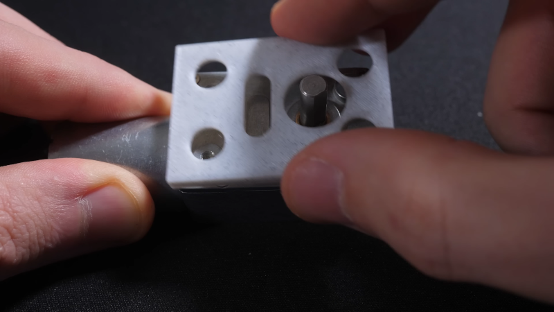
The good news is that 3D printing lets you iterate on your design until it is just right. The bad news is that you often have to iterate your design over and over to get things to fit together. It is a little easier if you are designing both parts, but matching sizes and positions on a printed part that fits something that already exists can be a pain. Sure, you can grab the calipers and make fidgety measurements — but [Maker Tales] has a different approach. As you can see in the video below, he takes a photo, imports it into CAD, scales it, and then uses it as a reference.
If you have one, you could, of course, scan the existing part. However, if you’ve ever tried that, results vary wildly, especially with cheap hardware. [Maker Tales] just takes a picture with his phone, trying to get as straight as possible and from a distance. Once in CAD, he makes one measurement and scales the image to the correct size.
This is one of those things that should be obvious, but you don’t always think it through. Of course, it is possible to measure everything precisely or — even better — if you have the original CAD or drawing for the part that has exact measurements. But compared to making numerous precise measurements, this method is a lot less work and gives good results.
If you are creating mating parts, think about shadow lines. Many commercial parts now have CAD models as STEP files if you want to skip the scanning.


A very simple way to avoid full size “fit test” prints is to start with a to-scale paper print out the most important dimensional slice of your model. Then move to a single layer (or two for stiffness) of the most important dimensional fit. The paper test lets you figure out if you were close at all and the one or two layer 3d print helps you ensure your extrusion tolerances are correct.
That’s great advice. Thanks!
Sometimes I design the part and then during slicing in Cura I move the entire part accept the area I want to test below the build plate. Then Cura only slices that piece so I can print it without printing the rest of the part. If it turns out good I don’t even have to open up the modeling software again.
For fit test – I usually print out of full component gcode – just cancel printing after 1 layer.
I found this works great to test the fit with “paper” thin slice.
Or you spitball it close enough and then use drills, sandpaper, knife, etc. to do the final fitting.
That’s one thing I find very curious, because I’ve seen engineering students 3D print parts for an exercise where they had to build some doodad. They would print, build, and then complain that the mechanism is binding up and doesn’t work – but the only problem is that they didn’t do anything to finish the part. Is that some sort of learned helplessness?
More likely they haven’t yet internalized that the digital world and the real world don’t always align.
That was the point of the exercise. Assuming that the part should be exact out of the printer, that there’s something wrong with the process or setup and trying to fix that (i.e. the cheap 3D printer) instead of fixing and fitting the part is still showing the same misunderstanding.
Same thing with laser cutters. There’s always a slight bevel in the cut, so if they make the top of a hole exact, the bottom will not fit, and if the bottom is exact then the top is loose. You have to “ream” the hole if you want it straight, which is simple to do, but somehow it doesn’t occur to the students that you can and you’re supposed to do that.
It’s easy to forget how simultaneously smart and stupid we all were when we were 20.
Tolerances are complicated AF. Most adults have no clue that they have no clue, think it’s all pretty simple. Engineering students are at least trying.
HS science and shop classes are necessarily nerfed. At that, they already scare off 75% of the population, who were promised ‘no math’.
It’s not digital world vs real one. It’s design world vs real. This was an issue on paper as well.
Don’t teach them to finish the part. Get them started on dimensioning and tolerancing. Then teach them to measure the part. Only then do they get the sandpaper.
That’s another thing. Some students gave it enough tolerance to not bind, then complain that the mechanism is sloppy and loose. The point is that 3D printed parts are rarely ready out of the printer, they’re not very precise to begin with, just like castings aren’t ready out of the sand. Even if you get your tolerances right for one machine in one condition, a month and a spool of filament later it’s different.
Heh…I did the same thing sorta when I copied the calibration nozzle for my PnP. I took a picture from the service manual of a picture of the part…then imported to CAD (initially inkscape but in the end fusion was easier). Since I knew the outer circle was 10mm I scaled to that and copied it. Then used my friend’s fiber laser to cut/etch a target from stainless that I put on the standard nozzle. Still needs some revision since I missed a couple things but it worked in principle. https://flic.kr/p/2orhcqw
Long ago I thought that a rig with graph paper and a camera mount would do this very well to “scan” parts into CAD. Seems like a good project to work towards :)
I might be mistaken but isn’t this the way that it is usually done? Because I’ve been doing this since 2010.
You have to take the common sense probagation rate in the youtube medoum into considderation. My estimate places it at around 10years. So yes 2010 seems about right
Congrats, Eduard! Yes, this is common but isn’t it nice to share proven techniques with those who may not have heard of it before? Seems like sharing projects, techniques, ideas, and (dare I say) hacks would be a great concept for a website!
What’s with the attitude?
For flat surfaces, nothing beats a flatbed scanner. No perspective or parallax issues, and you get accurate measurement in your graphic software without any calibration necessary.
Beat me to it.
Lay a couple of steel rules on the bed along the top & side of the part and you have a ready-scanned scale and accurate alignment too.
when I worked for an outdoor sign shop we used to do this sort of thing all the time. photograph the sign, take a measurement, bring it into Gerber, bring it up to scale, and now you have an existing sign to work with.
also, I did this to decide what size TV i wanted in my living room. photographed the wall, took the width measurement, and pasted in TV product photos at actual size (using the real product dimensions). no guessing whether the TV looked too big or small.
I would trust a scan to be considerably more accurate than a cell phone picture … and I have done both.
Scanners don’t deal well with objects that have any depth to them because the sensor is so close to the glass that there will be parallax errors.
There’s an old forgotten technique: lens correction in software. Take a picture of a graph paper and find out what sort of barrel distortion your camera has, then apply the reverse in GIMP or other.
Sticking parts on a flatbed scanner, [ Do kids these days still have those at home. :D ] it’s nice to know it’s already to scale, no tweaking of the image necessary.
I usually make a test gauge. Get the closest measurement I can and then print a test piece with a range of fits. For example, if I need to have a hole in a part with a specific fit. I will make a test print with several holes of slightly different sizes to see which fits best. Over time, you get pretty good at knowing your printer.
I recall using this technique in the mid-1990’s. I was always surprised how many draftsmen never thought of it, preferring to squint at rulers. Importing a raster image into CAD and drawing vectors over top of it is such an old feature. I’m glad to see new generations pick up on this handy technique.
“Why don’t you take picture it’ll last longer!”
– Pee-wee Herman
for simple placement of cylinders and squares and rounded corners on a plane, maybe i’m just in denial but … i don’t find it that hard to measure?
the time i find measuring really insufficient is when nothing’s flat, like when i’m working on two different surfaces in-plane to two different planes like 5 degrees off from eachother. and that’s exactly when it’s hard to decide on a proper perspective correction for a photograph.
i recently had to do one of those and i wanted a way to photographically capture it but there was no way that i could figure. i mean, i presume some sort of AI super camera could do it but i certainly couldn’t do it tracing a couple .jpegs from my phone camera. anyways i’m gonna accept my first infill print of that one (only a 2 hour print, thankfully) with just a thin rubber shim on one side, even though if i printed it again i would change one measurement from 2deg to 5deg.
i was really thinking at first this article would be about the printing variation. for me if i want pieces to *snap* or press-fit together, i will iterate 2 or 3 just trying r+-0.2mm, and still suffer a lot of trimming in post. that really tries my patience especially because if you do it in isolation you’ll get a different result than in your final print. but if i just need it to fit around something else, i give it an extra 0.3mm all around and i won’t even have to clean it up with the x-acto. easy pie.
If you can find a camera with a telecentric lens, they eliminate the distortion of perspective from reference photos. I.e. two objects of the same size appear the same size, even if they aren’t in the same plane. I haven’t found one in my price range yet.
I photograph the part on a sheet of grid paper with ten to the inch spacing, then bring the picture into Photoshop to correct the spherical aberration and then bring it into fusion 360.