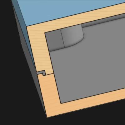
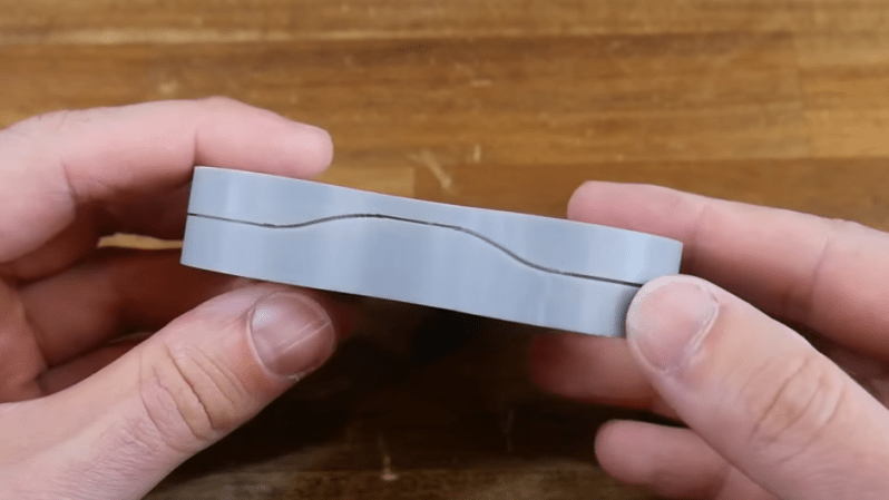
Some design techniques and concepts from the injection molding world apply very nicely to 3D printing, despite them being fundamentally different processes. [Teaching Tech] demonstrates designing shadow lines into 3D printed parts whose surfaces are intended to mate up to one another.
 This is a feature mainly seen in enclosures, and you’ve definitely seen it in all kinds of off-the-shelf products. Essentially, one half of the part has a slight “underbite” of a rim, and the other half has a slight “overbite”, with a bit of a standoff between the two. When placed together, the combination helps parts self-locate to one another, as well as providing a consistent appearance around the mating surfaces.
Why is this necessary? When a plastic part is made — such as an enclosure in two halves — the resulting surfaces are never truly flat. Without post-processing, the two not-quite-flat surfaces result in an inconsistent line with a varying gap between them.
By designing in a shadow line, the two parts will not only self-locate to each other for assembly, but will appear as a much more consistent fit. There will be a clear line between the two parts, but no actual visible gaps between them. Watch the whole thing explained in the video, embedded below.
This isn’t the only time design techniques from the world of injection molding have migrated to 3D printing. Crush ribs have been adapted to the world of 3D printed parts and are a tried-and-true solution to the problem of reliably obtaining a tight fit between plastic parts and hardware inserts.


I thought that line was for a screwdriver for me to pop the two halves apart. Learn something new every day!
You can see the same gap trick used in the fairings of a regular airliner. Ou brains can resolve minimal driscrepancies on a tight mating junction but can’t do it easily with thr width of the gap. Many other processing our brain does use relative measurements, like color perception, light intensity, temmperature, sound, etc
@ Andrew
Me too! Also was thinking why no one figured out something better since this is often dirt collector that requires cleaning.
Do you really need this on a 3d printed part?
Do you really need it on any part via any method?
If it makes for nicer looking and fitting 3d printed parts then you might well want it, but if you don’t care or want to spend a while with the sandpaper and filler for an even smoother look.
you don’t really need it. i have been putting together 3d printed parts with all of the disadvantages described in this article (“the resulting surfaces are never truly flat. Without post-processing, the two not-quite-flat surfaces result in an inconsistent line with a varying gap between them.”). the downside is just, it looks bad and it does a poor job of keepnig dust out and so on.
i’ve also done kind of the same thing, where i put a flat lid inside a little recess. like the article says, it nicely centers itself, and it doesn’t have a dust gap, and it doesn’t tend to get caught on things (so it’s effectively stronger), and so on.
i love that you don’t have to do a good job to get a useful result with 3d printing…but it is sometimes nice to get the advantages of lessons learned :)
Besides aesthetics and self locating, it can also provide some rigidity. Grab that 3D printed game controller and start twisting it, one printed without a shadow line is going to bend, flex and squeak far more than one with a shadow line.
Interesting. This is a keeper to think about and experiment with.
Over the years the times are many where I’ve taken a little flat end jewelers screwdriver and scraped out the hand gunk fills that groove that a damp towel can’t get.
Game controller smegma!
Nurple cheese!
I’m sorry, I realize you can’t unassociate those now…not sorry.
You all know what your hands were doing, right before you put them back on the keyboard/mouse.
And then open the controller and use a toothpick to get the rest. (:
That’s a parting line
Not if someone else leaves a comment after yours. ;-)
Looks awful and gathers grime. I don’t want to see the seams in my enclosures, let alone accentuate them.
Very helpful; have been looking for a way to make a neater seam between layers of printed components trays I’m magnetizing together. My brain is still wrapping around the geometry/steps required to make this work in Tinkercad with my rounded rectangles.