Calibration cubes have long been a staple for testing and adjusting 3D printers, but according to [Stefan] of CNC Kitchen, they’re not just ineffective—they could be leading us astray. In the video after the break he explains his reasoning for this controversial claim, and provides a viable alternative.
Such cubes are often used to calibrate the steps per millimeter for the printer’s steppers, but the actual dimensions of said cube can be impacted by over or under extrusion, in addition to how far the machine might be out of alignment. This can be further exacerbated by measuring errors due to elephant’s foot, over extruded corners, or just inaccuracies in the caliper. All these potential errors which can go unnoticed in the small 20 x 20 mm cube, while still leading to significant dimensional errors in larger prints
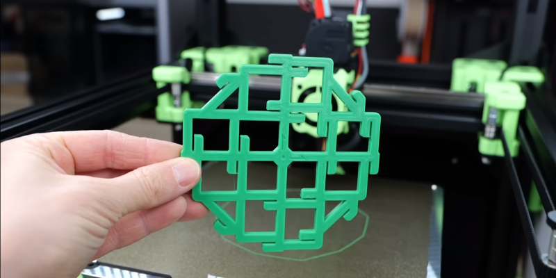
So what’s the solution? Not another cube. It’s something called the “CaliFlower” from [Adam] of Vector 3D. This is not a typical calibration model — it’s carefully designed to minimize measurement errors with ten internal and external measuring points with stops for your calipers. The model costs $5, but for your money you get a complete guide and spreadsheet to calculate the required of corrections needed in your firmware or slicer settings.
If you regularly switch materials in your 3D printer, [Stefan] also advises against adjusting steps per millimeter and suggests defining a scaling factor for each material type instead. With this method validated across different materials like PLA, PETG, ABS, and ASA, it becomes evident that material shrinkage plays a significant role in dimensional inaccuracy, not just machine error. While [Stefan] makes a convincing case against the standard calibration cube for dimensional calibration, he notes that is is still useful for evaluating general print quality and settings.
[Stefan] has always done rigorous testing to back his claims, and this video was no different. He has also tested the effects of filament color on part strength, the practicality of annealing parts in salt, and even printing custom filament.


If you want to calibrate the movement, then simply mount a (digital) caliper or dial indicator on the hot plate, and push it aside with the hot end. This gives you actual motion without artifacts caused by the extruded plastic.
Yeah this. The 3D printer folk should go talk to the machinist crowd more often rather than poorly re-invent the wheel yet again.
Dial indicators are a bit too small though, bigger is better. You can get 300mm calipers, they’re great for this sort of thing.
I could not agree more with this. Plus you have to add to it that youtube “experts” are 99.9% of the time experts in 2 things and jack left town. They can talk all day long but are basically puking back whatever their masters say. In most cases josef prusa. Most of these issues have been resolved literally decade’s ago in the machinists world but for some reason on a machine that can not hold a real tolerance it must be better than what modern day machinists use. It baffles me to be honest but hey I have uses for my 3d printer and they are getting fewer and fewer the more i use it because every time i use it i realize just how poor of a product it produces.
I will say the exception for me so far is with casting, they are really nice for that. Wow i went off on a tangent sorry.
TLDR ignore youtube “experts”
If your printer is producing poor results then you either have a rubbish printer or don’t know how to use it or calibrate it right. Even a basic cheap ender 3 can produce high quality prints if you spend time to tune it.
So why are you having print quality issues if most issues have been “resolved literally decades ago”? If you know so much and follow the way machinists do things then why is your printer producing poor results? Are you maybe another one that just likes to talk but doesn’t actually know what they are talking about?
My first 3D printer was a TronXY, a clone of the Anet 8 much loathed by YouTube experts.
I put mine together and it printed just fine. Looking at some of the YouTube reviews, I noticed they did the usual amateur fail of tightening the screws as they added them, rather than waiting until the end where you can check for square etc as you snug everything up.
But yeah, no surprise that they’d declare it a piece of crap. No subscribe for you!
I’ve still got it, I rebuilt it into a box to make it stiffer, but mainly to try ABS. Going to put Klipper on it since that seems the the latest coolness.
Don’t follow advice on calibrating your 3d printer because you think you know everything or it’s part of a conspiracy, get surprised when your 3d printer produces poor results but I capable of reflecting and realizing it’s your own fault. Shocked Pikachu.
Sure but you still need to calibrate material shrinkage, which is where prints like this come in.
The whole point is to eliminate measurements of the material and simply nail the measurements of the mechanics of the machine. Then you can dial in one thing at a time instead of going on a wild goose chase guessing—is it 30% mechanical calibration and 50% over extrusion and 20% shrinkage? Some other mix? Who knows?
I absolutely agree. Get the machine right first, then figure out the material properties.
And material calibration is actually the purpose of calibration cubes anyway — to figure out if the thing overfills and if the dimensions are right. Then you tweak the extrusion multiplier or hit your filament with calipers again.
(Or at least that’s the way we used to do it when I was a kid…)
I literally used a ruler and the largest move possible in the chosen axis. Terrible accuracy, but the error per mm is good enough.
Yes, your method will track hardware issues (balance, skew, torque, you name it). However, we are at the mercy and vagaries of materials’ inheritance. First off, not intended as a pun but, shrinkage is big issue. Moisture content, especially with PETG, plays havoc with extrusion.
As for calibration cubes, I never use them. Perhaps if I printed nothing but dice or boxes, but that ain’t happening. Even my mechanical designs are somewhat curvilinear so arcs are just as important as corners. Tuning pressure advance and flow rate are much, much more important. First, they’re quicker to print and secondly, I can always do these as spot checks as my filaments age, take on moisture, environmental impacts (winter dryness, spring higher humidity, etc).
2:28 in the video clearly discusses that the calibration is NOT just movement based. You would square your frame and set up the stepper motor motion during the build of the 3D print. But after that, many other factors come into play related to the material properties and extrusion rate (you are, after all, pushing plastic onto a plate and other layers of plastic).
Also, the method you described would be good for discussing straight motion, but the factor being introduced in the video is skew, for which you might be able to correct by measuring parallelism in the frame; but more likely you’d simply be able to detect by making a test print.
Exactly. And also, it’s not really possible for steps per mm to be off anyway – what, do you think the leadscrew is significantly wrong? As long as your math is right, any remaining error will be slop, backlash or cyclic errors, and plastic-related errors (thermal expansion, under extrusion, etc.). Nothing that can be fixed with a simple scale of the geometry.
This. Errors are usually a fixed value and not proportional to size. Using a 10mm cube as a gauge will be less informative than a 100mm gauge or larger.
I get this with laser calibration all the time. Draw a horizontal or vertical line with the laser and measure its length. A 10 mm line will show tremendous percent error, but a 400 mm line shows that the error is fixed and not proportional. Switch to a non-stretchable toothed belt and ensure it’s tight.
You can’t readily make a 300mm cube for the 3D printer, but you can print two 300mm flats and measure those lengths. You can get micrometer calibration rods on eBay for a couple of bucks, place one vertically on the bed and lower the head until it touches the rod – that’ll be much more accurate than printing a 10mm cube.
And don’t forget to measure the diagonals…
The gears and other parts in 3D printers are not precision machined and easily vary by a few percent between machines. And often even the approximate gear ratios aren’t known. For delta printers, things get even more complicated. That’s why people calibrate printers. Every printer I have ever used has required this.
Required it or you just think it required it? The only time my Ender 3 required steps/mm calibration was when I changed the extruder.
The parts in 3D printers, presuming you don’t just buy the cheapest you can find, are more than precise enough and do not vary by a few percent. It is relatively easy to find gear ratios and even with delta printers if your maths is right then you can just calculate the kinematics.
The reason people often use other ways of calibration without going and figuring out the maths is because it is quicker and easier, you take a formula you find online, take a measurement and then you get the value to adjust it to. It is a quick way but it doesn’t mean that figuring it out just using maths doesn’t work.
Even if your leadscrew is perfect as many printers have things like belt based gearing between it and the stepper on some axis you could end up off there – that belt drive pulley that is 0.01mm incorrect in radius makes its circumference around 6x that out, and as it probably still has to rotate many many times to drive the screw through the full range of motion that could add up a lot of total error.
This is the real world, so its always worth assuming the production isn’t nearly as ideal as you expected and measuring that actual movement per step. Though you definitely shouldn’t be calibrating the motion with a printed result on its own – get the motion right in isolation first and eliminate all the plastic variables. Then if you actually require more tuning down the road for particular filaments you have a great baseline to start from.
I don’t bother much with test objects anymore. Probably only printed one benchy.
They are probably fine for first couple times using the printer but I personally think they are more of a waste for repeated calibration or benchmarks.
My advice has always been print real objects. The things you are going to print commonly.
Design something to fit a part you have laying around…see if it fits. If not find out why.
My personal opinion is that people blame things like die swell and shrinkage a lot more than they are actually a problem. Usually the issue can be traced back to overextrusion or temperature/ambient issues.
Or…just cheap unpredictable filament.
yeah my thought exactly. i think someone calibrating with test objects has to have unreasonably high expectations or they wouldn’t do that. i just print the things i need, knowing that each session may turn out to have been a calibration run in hindsight. such an enormous number of variables, and i just am always aware that i’m going to have a little uncertainty in how the printer will render each shape. there’s no magic dance i can do ahead of time to remove that uncertainty.
You forgot about the 3D designer!
Half joke, but many objects seem to require tolerances half way between a brag and a bad idea. Like yeah, it’ll close if you can print it with better than 0.1 precision. But it would also have the same results if designed with 0.5mm gap, and then everyone could print it with good result. Half the printers have a worse than average calibration.
Samen here, I set the steps per milimeter once. I did not even print a benchy but just tested if what I printed was within the spec I need. I usually print smaller parts, casing for a PCB stuff like that. Dimensions are roughly within 0.25mm which is perfect fine for 99% of the things I do.. as long as the lid fits, and the PCB can be screwed at the designed holes I am good togo
I’m a big fan of the “if you can’t make it accurate, make it adjustable” philosophy, or more usually add some “slop”, like slightly over size the PCB screw holes to give you some wiggle room.
And as you point out if print 2 parts on the same machine, they’ll fit together fine even if they “wrong”.
I set shrinkage to 0.5%, works fine for most PLA & PETG. Only time I’ve really fiddled with it was to print a part with a fine thread, that needed to be spot on.
“the required of corrections”
For a new filament I run a temperature tower with bridging test. Then a single wall cube in vase mode to check flow. I’ve started putting down a 2 or 3 layer raft instead of using an ABL map. It gives a flat surface that’s way higher precision than a 25 point map.
this is a cash grab. the video an informative commercial to sell a product. money money money to reinvent the wheel.
Yea don’t pay $5 for the model. On Printables search ‘calibration snowflake’ and google skew calculation. you get to learn a lot more about skew and not waste $5