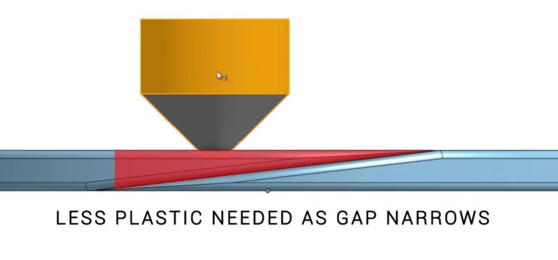
One unavoidable aspect of FDM 3D printing is that each layer consists out of one or more lines that have a beginning and an end. Where these join up, a seam is formed, which can be very noticeable if the same joint exists on successive layers. Taking a hint from woodworking, a possible solution is now being worked on that involves scarf joints. This research is covered by [Michael Laws] in a recent Teaching Tech video on YouTube, where he also details his own printing attempts with a custom 3D model, and a guide by [psiberfunk/Adam L].
The idea for a scarf joint was pitched practically simultaneously by [vgdh] on the PrusaSlicer GitHub, and [Noisyfox] on the OrcaSlicer GitHub. The basic idea follows the woodworking and metalworking version of a scarf joint, with the overlap between two discrete parts across two heavily tapered ends. As with the woodworking version, the FDM scarf joint is not a silver bullet, and with the under development OrcaSlicer builds a lot of the parameters are still being tweaked to optimize the result.
If it can be made to work, it could mean that scarf joints will soon be coming to an OrcaSlicer and PrusaSlicer release near you. Theoretically it should mean faster prints than with randomized seams as fewer print head adjustments are needed, and it may provide a smoother result. Definitely an interesting development that we hope to see come to fruition.


I wonder how well bonded the scarfs end up, depending on the method used to adjust plastic extrusion vs head motion to create them it might end up having a structural benefit as well – that slightly longer heat dwell vs the thickness of the existing layers it is melting into maybe helps bond across the layers at each scarf. May even become worthwhile to deliberately skip up and down layers a bit with the scarfing technique if so, combined with the rolling hill style layer printing concepts as well perhaps… I doubt it will bring 3d printing to having the same material properties in x,y and z, but it could really help stop that layer crack propagation that leads to rapid part failure.
I have no idea what precision 3d-printers can achieve, but if they could increment their Z height at fractions of the layer height, you could do the described technique only for the bottom layer, then slowly spiral up.
Look up “vase mode” if you haven’t already heard of it, it does essentially exactly what you just described!
but it only does it for a single wall thickness, as soon as you add further wall thickness, vase mode doesn’t work because it’s no longer a continuous single line of filament, so the seams are back again.
That’s assuming you have one continuous path along the layer – with infill and all.
.05 mm layer heights is achievable with most FMD printers.
As for ‘spiraling up’ the issue here is that only works for single-wall objects. If your object has an inner and outer wall (and you’ll need to infill a percentage of the gap between) it can’t be used as ‘spiraling’ is a ‘single constant move across the layer’ where the above would require starts and stops to build disconnected sections.
Now, single wall objects can have a pretty thick wall (depending on your nozzle diameter) but its on the order of 1mmish max.
The precision in Z height is more than adequate for your idea. Doing this for the inside walls only will make it invisible too.
I tick a box for “”random seam placement” and, yet again on HaD, wonder “WTF is the point of the article?”
Random placement only gets you so far, if this can become easy and practical it does promise a better finish. All the random does is spread the printing flaw at the joints around so it is not as easy to see, this concept actually improves the appearance of that join and it should be useable on a random seam location as well for even less noticeable impact on the finish.
This is actually a progression of 3D printing technology.
Random scatters the seam into a bunch of seam zits. Scarfed joints would feather/fade the two ends together so they overlap slightly with no hard seamline, so even with aligned seam, it becomes almost invisible
You write “The idea for a scarf joint was pitched practically simultaneously by [vgdh] on the PrusaSlicer GitHub, and [Noisyfox] on the OrcaSlicer GitHub.” but that is completely inaccurate. The scarf seams were first proposed by me, Michael Lew, on both the PrusaSlicer forum, Github and on Reddit several months before vgdh became involved. Maybe you didn’t check…