Cheap uninterruptable power supply (UPS) boards that take Li-ion cells of some description seem to have cropped up everywhere the past years. Finding use in applications such as keeping single-board computers ticking along in the case of a power failure, they would seem to be a panacea. Unfortunately most of these boards come with a series of fatal flaws, such as those that [MisterHW] found in an LX-2BUPS board obtained from AliExpress. Worst of all was the deep discharge of the Li-ion cells to below 2 V, which took some ingenuity and hard work to fix this and other problems.
![The patched up XR2981 boost IC with MCP809 reset IC installed. (Credit: [MisterHW])](https://hackaday.com/wp-content/uploads/2024/05/upload_34f9a5c70d7738a67185359c3110505b.jpg)
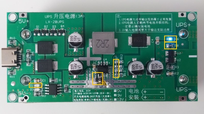
The final coup de grâce was the eviction of the red LED (D6) and replacing it with the blue LED from D2, to stop the former from draining the cell as well. With these changes in place, no-load power usage dropped from nearly 900 µA to just over 200 µA, while preventing deep discharge. Although this board now has a second life, it does raise the question of what the point of these cheap UPS boards is if you have to spend money and time on reworking them before they’re somewhat acceptable. What is your go-to solution for these boards?


“…What is your go-to solution for these boards?”
Easy–don’t use them under any set of circumstances.
…Unless you have a death wish…
Even better, would be if someone were to create a new PCB with the fixes in it and release it to the world. Cheap Chinese manufacturers would steal it (as is customary) and shortly there would be improved cheap UPS products on AliExpress…win!
Also…these LiIon cells being used must not have safety PCBs which shut off current if the cell voltage goes too low…
The problem is the Chinese manufacturers will start omitting parts, or using substandard/out-of-spec parts, to shave costs, and we end up back in the same boat.
I actually reverse engineered a WiFi light switch that went up in smoke a few years ago.
I noticed a 0Ohm on the circuit diagram that didn’t look right and it was where the rectified mains had found a path through that caused the combustion of the circuit.
When I looked at the 0Ohm closer? It was supposed to be a diode, it was even marked on the PCB as such. Someone cheaped out at one point, realised the thing would work with a link instead of a diode and switched the part, probably saving a cent, not realising their was a very good reason the original designer put a diode in originally.
“not realising their was a very good reason”. Thare was? Ware? Over they’re?
The same manufacturers are notoriously bad at fairness and reciprocity. But instead of being their useful idiot in dedicating time to normalizing their practices, why don’t you track down the original creators and convince them to put their design up on github.
No problem then to log an issue and provide a PR with the listed changes.
it always amazes me to see people make such crap – surely it wouldn’t have cost much more to do it right in the first place…
I kinda wish there was something other than the tp4056 for charging. Doesn’t it max the cells out at 4.2v? I’d rather be able to choose 4.1 or 4.15 or 4.05 if I wished. Use much larger battery and make it last longer.
Realistically you want to use a proper charging IC with power path control, like the ones used Laptops, that will automatically switch between battery power and wall power. This is the only acceptable long term solution IMO. For example: TI BQ24610
Why? Are you concerned that load step changes will affect cell state? Other than poor regulation it should not make a great difference, and since the cell is kept at a high state of charge anyway it will have a shortish life either way.. but I’m speculating and actually curious?
I’d like to be able to select 4.3V as well.
MP2696 BATT_REG[2:0] does allow selecting 4.1V and 4.3V, but there’s a catch. As elaborated in https://github.com/MisterHW/EVAL-MP8862/ , MPS label “OTP” what is actually an obligatory factory programming step tied to their calibration process.
Here, it’s an I²C job.
Nice, thanks, that’ll be useful if I can find them at a decent price and in stock :)
@Miles said: “I kinda wish there was something other than the tp4056 for charging. Doesn’t it max the cells out at 4.2v? I’d rather be able to choose 4.1 or 4.15 or 4.05 if I wished. Use much larger battery and make it last longer.”
Once you add a micro-controller with GPIO, ADCs, and current shunts, you can do anything with an I2C power bank controller.
The article mentions some chips from Monolithic Power Systems (MPS), Excerpting and embellishing a little:
– MP2698 “ALL-IN-ONE SOLUTION IC W/ 3.6A BOOST AND 5.0A FAST CHARGING” (NSFND)
https://www.monolithicpower.cn/cn/documentview/productdocument/index/version/2/document_type/Datasheet/lang/en/sku/MP2698/
– MP2696A “SW CHARGER W/ I2C CONTROL, 3A BOOST”. I2C-Controlled, Single-Cell Switching Charger with Power-Path Management and 3.6A Boost Output. This one is a gem. But you will need some extra code if you assume the end user will insert “dumb” cells with no thermal sensing (always assume the worst).
https://www.monolithicpower.com/en/documentview/productdocument/index/version/2/document_type/Datasheet/lang/en/sku/MP2696A/
– MP2639B “1S Cell Li-ion or Li-polymer Switching Charger Compatible with Wide Input Range and Integrated Programmable OTG”
https://www.monolithicpower.com/en/documentview/productdocument/index/version/2/document_type/Datasheet/lang/en/sku/MP2639B/document_id/4934//
For example, MP2696A has a no-load Iq = 1mA but with an extra microcontroller that handles the no-load detection and checks whether the target device (e.g. a Raspberry Pi) is in shutdown, the UPS can switch to idle mode with 25µA current draw.
TI has a bunch of interesting parts too.
More than likely, one guy designed it very cheaply (from a parts and a design time standpoint) in a few minutes several years ago and 100 companies just copy the design and resell it, not having any idea how it works.
One good thing with the tp4056 is that with low enough loads, it actually shuts down once the battery is high enough, and le’s the voltage come down before retriggering. i.e.. it cycles rather than hold at the peak all the time.
I would just use a battery that had built in protection. Solder to the battery terminals if needed.
My goal with lithium is to keep everything between battery and protection module completely stock and non-hacky. Do whatever you want *after* the PCM, but touching anything before that is way too hacky for me. Even with a PCM, for big batteries, you might as well also have a fuse.
I prefer not to do stuff where a bad solder joint burns down houses.
At most, I’ll use those little USB charge modules with a built-in protection chip, but I never use a lithium that doesn’t go through a purpose built hardware protection chip.
From ian 42. above–
“it always amazes me to see people make such crap – surely it wouldn’t have cost much more to do it right in the first place…”
It’s not a question of doing it right “in the first place”; it’s the need to sell something…period. And, by the way, this extends all the way to AliExpress. They (it) doesn’t care, and furthermore doesn’t want to know that what they’re selling is crap.
There is NO electrical/electronic engineering going into any cheap electronic product any more, and furthermore, there hasn’t been for a very long time.
Want to know why your battery (ies) for your Harbor Freight drill don’t last long at all?
Want to know why your cheap “12-v battery maintainer” kills your battery rather than ‘maintaining’ it?
The answers to these questions, and far too many more, can be found by simply taking the “chargers” apart, and seeing what a piece of crap they really are. (Fair warning: you may have to go so far as to re-creating the circuit diagram from the PCB board. The “maintainer” which killed two of my expensive 12-v AGM/(very expensive deep-discharge) gelcel batteries was filled with sophisticated components–none of which were connected together in anything approaching a minimal ‘battery-maintainer’ design…but it looked good, from a distance!)
Fair warning…
There’s lots of open source software which is substantially better than the proprietary alternative, but being open source means no money, no money means no marketing budget, which means the unfamiliar never hear about it. Same thing with cheap crap, higher margins so higher marketing budget so higher sales.
i don’t care about anything in this article except the photo of the rework. it’s like a surfacemount dead bug! wow!
Came here to say the same. As someone who does a lot of SMT rework deadbugs…I approve. At least based on what I see in the pic.
I think if you actually specifically used it as an UPS and with large enough batteries it might be OK most of the time: If the connected system can shutdown gracefully on notice then you really only have to worry about that idle current an a milliamp really isn’t much to worry about for a very long time with appropriately sized batteries.
If there’s no communication with the client then it’s absolutely a fire trap. If the client ignores the warning it’s dangerous. If the batteries are tiny pouch cells, the idle power is dangerous.
Wow this is timely for me, I impulse bought one of these exact boards a month ago. I thought it could have built-in lipo protection but was not surprised to see it did not. Once the battery gets low enough it keeps pulling a substantial amount of current but not outputting a 5V. This definitely a solution for that! It is a shame they didn’t include the protection circuit, because using protected 18650 would A) certainly not fit in the holders (unprotected cells are crazy tight) B) cost a ton, comparatively ($12 vs $5).
Just use 2 diodes.
What would happen if I just remove D6 and R8? On a different circuit, when there was no control provided on an internal LED, one of the comments suggested to just shear off the LED from the board. Wouldn’t that work here?
Hi,
Many thanks for the information on the LX-2BUPS module.
Overall, the implementation seems reasonable, and the input side load sharing circuit works well.
The power rating is perhaps a little optimistic, particularly on the 12V version, at 15W with an 80% efficiency, the 5V input current will be around 3.75A.
On the 5V version, if the DC input goes above 5V, the output will also increase. This is covered in the advert for the module.
The noise level is relatively high, particularly on the 12V version, but this is to be expected with this type of boost regulator without additional filtering circuity.
On the main points that you identified.
– Over Discharge
I am not sure that your understanding of the behaviour in the over discharge state for the XB7609A is correct. At VDD = 3.6V, the device will not be in the over discharge state.
Internally the SB7609A is likely to be similar to the DWO1 protection IC, which has external MOSFETs.
On the two LX-2BUPS modules that I have, I checked the current drain from the battery when the voltage is below the “Over-discharge Detection Voltage” of 2.4V and the measured current was 3.6uA.
Therefore, my understanding is that the LX-2UPS will not inherently cause over-discharge beyond 2.4V.
– Standby Current
I agree the standby current is not ideal.
At a battery voltage of 3V, I measured approximately 1mA for the 5V version and 14mA for the 12V version.
In practice, the use case for the module would be with it connected to a load and it would only be drawing current from the battery when the primary 5V DC input fails.
If the module is to be kept in storage, then it would probably be acceptable to just remove the battery.
Where can I find the schematic for the LX2BUPS?
Hi,
I have not seen a schematic on-line. I have posted a basic block diagram with a few observations in the following forum.
https://www.eevblog.com/forum/renewable-energy/chinese-lx-2bups-ups-module-emi-issues/msg5621833/#msg5621833
I was intent on using one of these as a powerbank for guitar pedals, which seems to work well so far; I am however not to keen on leaving the thing always on so I thought about adding a toggle switch to decouple the batteries.
Anyone have a recommendation on how and where to implement this? The cells (taken from an old laptop battery) do not exactly pop in/out easily.
Hallo,
ich habe ein Bord bekommen, das “Angeblich” überarbeitet worden ist.
Wo sehe ich Veränderungen:
Bei Q1- Q4 steht der wert “A19T”
Bei U2+U3 steht der wert “MMG1X”
Ist dies nun besser oder schlechter?
Zur Info, ich habe die 5V Version, für meinen Bewegungssensor, falls der Strom ausfällt oder versehentlich abgeschaltet wird.
Hoffe auf ein paar gute Tipps und Info`s.
Dankeschön.
Why couldnt y ou put the values of these items like the “better resistors” etc and explain a bit more of what you were doing would have been very helpful. NIce none the less but I do wish you would have done that