How hard is it to make a fully standalone SDR? [101 Things] shows you how to take a breadboard, a PI Pico, and two unremarkable chips to create a capable radio. You can see the whole thing in the video below.
The design uses a standard Tayloe demodulator. There’s also an encoder and an OLED display for a user interface. You might also want to include some PC speakers to get a bit more audio out of the device.
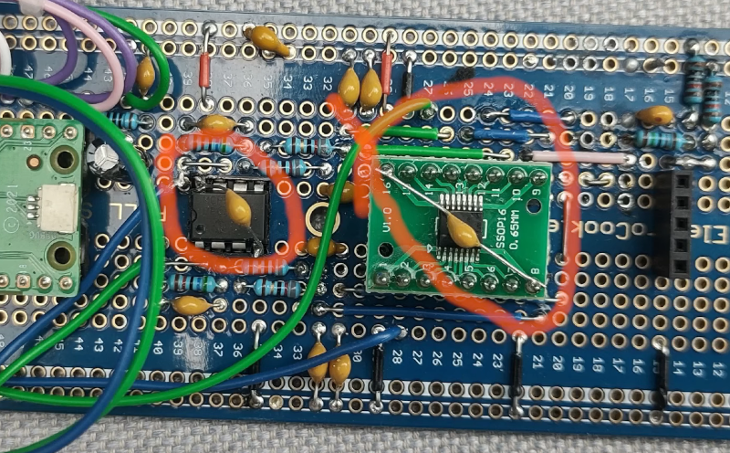
The PCB breadboard in question seems to work at higher frequencies, although the construction is very careful not to have long wires. This is a simplified version of an earlier design, so the software on GitHub is mature and can decode AM, FM, and SSB. The radio tunes up to around 30 MHz.
If you don’t want to change the program, you can download precompiled firmware, too. This would make a great weekend project, and there’s even a 3D-printed case design you can download for aesthetics. You may need to order a few parts ahead of time, so plan accordingly.
If you want even fewer parts, it is possible. Need an antenna for your slick new shortwave? We tried a few.


This is worthy of a smd or through hole parts PCB. Not just fly wires and a breadboard. It has the potential to make pricey low band radios envious.
I have virtually no expertise in all of this, but I wonder how much this project could gain from the new RP2350..
the rp2040 was ignored for sdr purposes for a long time due to its adc bug. that being fixed with the rp2350 and a huge boost in clock frequency would make a massive improvement. Probably not too difficult to port the code over. I imagine you won’t have long to wait until someone does.
the RP2350 also have floating-point math, something that RP2040 don’t have.
Interesting, possibly make a useful IF stage
i don’t like the phrase “two unremarkable chips”.
it’s a 4×1 multiplexer/demultiplexer (solid state relay, i guess. speced at 5ohm when connected) that feeds a dual op amp / comparator with capacitors on its inputs. i don’t really know how it works but i assume it switches the antenna signal between the 4 op amp inputs at some multiple of the selected frequency. i’m surprised they can pass an unamplified antenna signal through the multiplexer.
This. For all I know, a LNA stage along with preselector or at least simple LPF would allow for lower gain needed at the opamp stage, resulting in better noise figure along with the possibility to use slower and hence less noisy opamp.
There are LPFs on each output of the analog mux.
Sure. But you should consider the switch a sampler, which converts a continuous function or signal into a discrete sequence just like an ADC for instance, so you need some LPF to avoid aliasing effects. Nyquist.
That’s what the caps on the opamp do. They implement an integrator which serves to low pass the mixed signal.
willmore: Yes, but those are useless, as the aliasing signal that originated from switching the analog switch is already in their pass-band. In fact, LPF will not cut it, you need to use tunable BPF before the analog switch. The pass-band of the BPF should follow the local oscillator frequency/4 (which happens to be the frequency we tuned for) in order to avoid creating unwanted artificial signals from off-band frerquencies. Perfaps a varicap based low Q filter driven by the micro via poor man’s low-pass filtered PWM output would suffice.
You are wrong. The switcher is actually a mixer and it works in quadrature, meaning you get both positive and negative frequencies without them mixing together as with a simple superhet. Read up on quadrature detectors, sometimes called Tayloe detectors.
This arrangement in fact allows one to use a plain LPF after the mixer, which tracks with the tuning, eliminating need for BPF. As there is no LNA on front of mixer, it also can’t get overloaded by OOB signals. The sampling is also differential and can be double balanced, eliminating power supply and ground noise.
The only drawback is that for higher speeds you need a really fast switcher. Many modern receivers do this in silicon, though. Also, it can be used for transmission.
This is a standard Quadrature Sampling Detector, widely used in SDR applications for many years. Google “SoftRock” and you’ll find an almost identical circuit used. The main difference is that here the RP2040 is used to generate the switching signal rather than the usual Si570 or Si5351 programmable oscillators.
The trick is that the 1:4 analog mux is sampling the RF onto thos 56nf caps at the 4x the LO rate, effectively tuning and detecting at the same time. The opamp afterwards is merely boosting the gain at baseband audio frequencies. If you read the datasheet for that analog mux you’ll see that it has plenty of bandwidth for sampling in the HF frequency range.
Unremarkable as in they aren’t not SDRs on a chip…
It cuts the quadrature (I and Q) into 4 phases and then sows them back together for a complete sinwave. Simples. :)
Amazing
How do you even start to learn this stuff?
Read.
Do.
Repeat.
Eventually, you get it. But like learning anything new, be prepared to feel stupid for the first 50 hours.
you can start almost anywhere so long as you keep asking questions and seeking the answer to them. personally, i would recommend starting at trying to understand ‘time domain’ vs ‘frequency domain’ and the fourier transform between them. i got my start on that from the opening chapters of The Scientist And Engineer’s Guide To Digital Signal Processing, which is a fantastic free book https://www.dspguide.com/
but there’s also all manner of introductory material specifically about radios
the fundamentals are the sort of thing where it helps to be exposed to it again and again from different directions before it really sinks in. like to really ‘believe’ the nyquist theorem took me a few exposures.
Great book, thanks for the link!
Start at pysdr.org
Given that video thumbnail schematic, I’m not going to watch it.
If you want to learn about this, QRP Labs (Hans Summers) has a terrific set of kits that use this Tayloe mixer front end.
One very accessible one is https://qrp-labs.com/qcxmini.html
The newer QDX does the whole ADC/DSP/USB thing https://qrp-labs.com/qdx.html
Go read the manuals: They are works of art, and have full schematics and excellent descriptions of the operating principles.
And, yes, a preselector is very much desired.
Can totally confirm this. Have purchased and built a few of his radio kits. The documentation is sooooo good. Not just how it’s built but why, what the design tradeoffs were, and excellent documentation of the entire signal path and how to trace and trouble shoot it.
Great addition to RTL-SDR which can only go down to 30Mhz, but needs waterflow mode.
That depends on which dongle you are using.
Fun facts from the Pico RF world…
You can use DMA sniffer and a buffer with pregenerated phases as a NCO with sub-Hz resolution.
You can use PIO to toggle not only output value, but also pin direction. If you toggle between IN and OUT-GND and connect this to the antenna, you get superhet. Add a LNA, amplifier, over clock ADC a bit and voila, you just made a superhet SDR with two BJTs and some passives. The LO does not really leak in this arrangement as a bonus.
It’s sadly single ended, so the noise from board SMPS spoils the fun unless one adds an external LDO and disable the SMPS with the correct pin.
While a far cry from a differential setup, it’s still totally useable for simple remote control. Or receiving 100 MHz FM with some overclock. Or 1 MHz AM. Whatever you like.
Could you elaborate on “You can use DMA sniffer and a buffer with pregenerated phases as a NCO with sub-Hz resolution.” or point to a place that explains it how ?
Thanks !