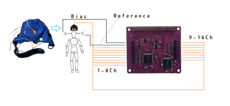
We’ve previously covered the PiEEG, an affordable brain-computer interface (BCI) shield designed to connect to the Raspberry Pi. The open source project developed by [Ildar Rakhmatulin] is intended to allow students and hobbyists to experiment with detecting electroencephalography (EEG), electromyography (EMG), and electrocardiography (ECG) biosignals — unlocking a wide array of applications ranging from assistive tech to gaming.
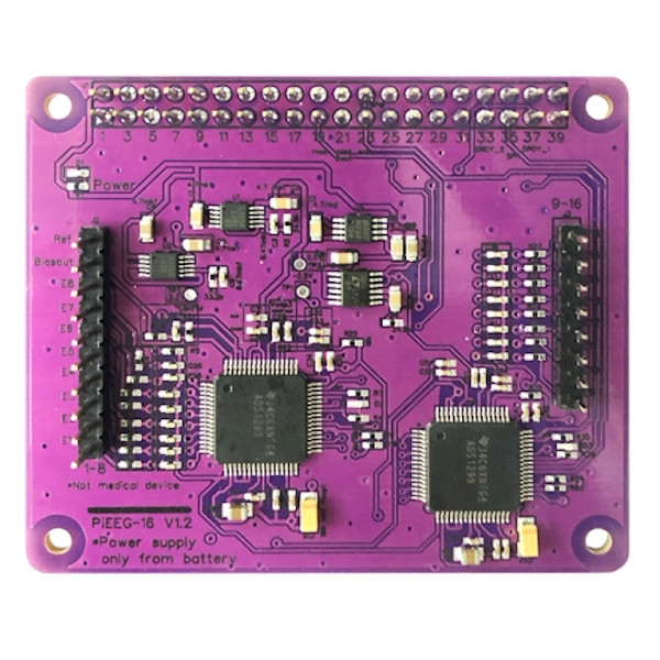
Now, the PiEEG hardware has been upgraded to detect sixteen channels via either wet or dry electrodes. The new board, referred to as the PiEEG-16, offers up the same ease of use and features as its predecessor, including the ability to read out signals from the device using Python scripts. Compared to the eight channels supported by the previous generation of hardware, the PiEEG-16 promises to provide the fine-grain data required for more complex operations.
 Since we last checked in with the PiEEG back in 2023, [Ildar] says the project has attracted plenty of attention. To help document how the community is using the capability offered by these BCIs, he’s added a page on the project’s site to show off what folks are building with the technology.
Inevitably, some express concern when talking about non-professionals working with brain interfacing hardware. But the project’s documentation is quick to point out that efforts have been taken to make the endeavour as risk-free as possible. The most important thing to remember is that the Raspberry Pi and PiEEG are intended to be powered by batteries so as to remain completely isolated. Similarly, there’s no need to connect the devices to a mains-powered computer, as everything happens on the Pi itself.
Even still, it’s made clear that the PiEEG-16 is not a medical device, and has received no formal certifications. If you want to experiment with this technology, you do so at your own risk. Just something to keep in mind…no pun intended.


Well I guess they assume you have mains isolation transformer then you can plug it in to a mains powered device
There are monitors here and there which are powered by 12v power supplies. Probably could get one of those and run it off of batteries. But, yeah, No Mains to the Brains might be a fair safety slogan here,.
You right, only monitor also should be conencted via 5 V, this is written in the manual, on the website, github, in articles, on the device itself, etc.
well to be fair its not 1961 anymore and your TV’s chassis probably isn’t connected to hot though its 2 prong outlet …
Are you not familiar with WiFi? There’s absolutely no reason a mains powered device would need to be connected to this.
Thank you! Yes, or it can be used wifi. In general, it is written everywhere that under no circumstances should either the Raspberry Pi or the screen be connected to the network.
In instructions, in general, everywhere, liability in the website, in descriptions, in the manual, in GitHub, and also on the PCB board… It is written that the monitor can only be used when powered by a 5 V battery, why do you write about wall power?
They do indeed spend more screen area on disclaiming any sort of liability then on giving some hints what is a safe way to use the thing. I followed a link to gitlab, because I was curious about the schematic (It seems to lack any sort of decent protection circuitry on the inputs, judging from the minimal photograph) but I don’t see a schematic on gitlab. (Did not search long either). They do mention on gitlab that this thing should be powered from batteries only, and that makes the whole contraption quite silly. It makes much more sense to hook up a frontend like this to an ESP32, (or an even lower power uC) and then power that from batteries and connect to WiFi, Bluetooth or similar. There is no need to put the whole power hungry PC on battery power, and it’s also far to tempting to plug in some mains powered power supply.
And sure, this thing probably would not kill you (quickly), but that they’ve apparently not even tried to make a decent front end with built in protection circuit makes the whole circuit “proof of concept” only and not fit for use on humans.
Why use ESP32 if you can transfer data via WiFi directly via Raspberry Pi?
It has a reduction of 10 to 100 times in battery power, and you can probably go one or two orders of magnitude lower if you’d really put some effort into a low power solution.
Second reason is size. This think looks like it to be used as a wearable. Both the raspi and the necessary very big battery make it a nuisance to carry it with you. With a bit of proper design, the whole thing could fit in a matchbox and have a (much) longer battery life at the same time, which makes it easy to for example wear it as a necklace
yes i agree with you, only the purpose of pieeg is for study, not for creating real prototypes or wearable devces
RaspberryPI is better because in Python, almost in real-time you have access to register ADS1299, so you can quicly change the Python script (change speed, amplifier stage, etc) and see the result, it is much easier and faster than using ESP32
Complete non-argument.
There are plenty of microcontrollers that have more processing capabilities then you would need for servicing a slow ADC such as this.
“Changing python” code is also amateurish, and not any quicker then doing it the decent way. The proper way is to make up a command set for a data communication protocol (inclusive gain settings etc) and put that in the microcontroller. You write that code once (and in a less power hungry programming language for a battery powered gadget, see https://hackaday.com/2024/09/10/assessing-the-energy-efficiency-of-programming-languages/
And then you can use the raspi for the backend. From a nice GUI with touch screen buttons to set the gain (including an auto range option) to data logging. And you can change all the code in the raspi while still wearing the wireless frontend during software development.
You roght, but this devive only for study, not for for wearble applciations.
Actually soon wil lbe avaialble new veriosn of this device with BLE data transmition
https://github.com/Ildaron/ironbci
Can you share the URL for the schematic, I find myself unable to locate it…
Will do soon!
i agree that they should have used a smaller cpu. i really think it should run simple software just to get the data stream down to something that can be sent easily over wifi or bluetooth, and then the more complicated / configurable processing should happen on a ‘big computer’ (PC) somewhere else.
but in my ignorance, i don’t know what kind of ‘protection circuit’ you would expect? what kind of events are we protecting against? i don’t know much about analog front ends — is feeding current back to a high impedance input really something that can happen? is there like something you need to do to isolate the feedback loop of an op-amp from the input signal? i would have thought you would have to do a pretty good job of preventing that, just to get a usable signal. even if you didn’t care about safety. ???
THank you for you suggestion, Here all pins connected to ADS1299 it is ADC, and power supply only from 5 V baterry
It runs linux. SSH into it and spawn a xterm session. Works across the Internet, even.
I had a look on it: one STM32 board, one HC12 bluetooth board, and finally the ADC board, all sandwiched with tall connectors, where a simple bluetooth micro controller with the two ADCs would have suffice, would have use much less energy, and would have be waaay smaller.
Is there any reason why it was built like that ?
Hi Actually, now I replaced HC12 bluetooth board to STM32WB with antenna on the boards and works well, about sandwich format, this gives a cleaner signal because it is easier to separate the analog and digital grounds, and it is generally convenient. Or I am wrong ?
Great technology.
I’m excited got to try this.
I’ve watched the movie Frankenstein, so I think I know how this works. I presume I should use use an outside aerial to capture the excess energy flowing during a thunderstorm for maximum effectiveness.
Ohhh!! first positive comment!! thank you, looks like Hackaday it is a great place to receive many expert and critical comments