As electronics rely more and more on ICs, subtle details about discrete components get lost because we spend less time designing with them. For example, a relay seems like a simple component, but selecting the contact material optimally has a lot of nuance that people often forget. Another case of this is the Miller effect, explained in a recent video by the aptly named [Old Hack EE].
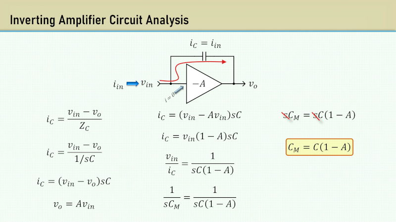
Put simply, the Miller effect — found in 1919 by [John Milton Miller] — is the change in input impedance of an inverting amplifier due to the gain’s effect on the parasitic capacitance between the amplifier’s input and output terminals. The parasitic capacitance acts like there is an additional capacitor in parallel with the parasitic capacitance that is equivalent to the parasitic capacitance multiplied by the gain. Since capacitors in parallel add, the equation for the Miller capacitance is C-AC where C is the parasitic capacitance, and A is the voltage gain which is always negative, so you might prefer to think of this as C+|A|C.
The example uses tubes, but you get the same effect in any inverting amplification device, even if it is solid state or an op amp circuit. He does make some assumptions about capacitance due to things like tube sockets and wiring.
The effect can be very pronounced. For example, a chart in the video shows that if you had an amplifier with gain of -60 based around a tube, a 10 kΩ input impedance could support 2.5 MHz, in theory. But in practice, the Miller effect will reduce the usable frequency to only 81.5 kHz!
The last part of the video explains why you needed compensation for old op amps, and why modern op amps have compensation capacitors internally. It also shows cases where designs depend on the Miller effect and how the cascode amplifier architecture can negate the effect entirely.
This isn’t our first look at Miller capacitance. If you look at what’s inside a tube, it is a wonder there isn’t more parasitic capacitance.


Its a very interesting and a relatively simple to identify and explore effect if you’re doing any kind of high frequency switching. Its pretty intuitive as well, even if you don’t go into all the math, and experiencing it really opens your mind to the considerations of parasitic capacitance.
Its also the bane of anyone making a high speed FET drivers.
“…how the cascade amplifier architecture can negate the effect entirely…”
Autokorrupt? You mean cascode amplifier
I feel like more time could be spent on this idea because to an engineer, it’s good to know about the effect, but it’s more important to know how to combat it. But maybe that gets into amplifier design too much.
It was originally cascode, but someone’s autocorrect got to it. Changed back for now ;-)
In a stroll through Wikipedia, I discovered an interesting historical linkage. The term “cascode” is from Hunt and Hickman in 1939. Fastforward to today, and there is a multigate transistor (or multigate device) that was invented, in part, to address the Miller Effect, but the multigate device is integral to the FinFET, tri-gate, and GAA (gate all-around) transistors in the newest small-nanometer digital chips (sub-30nm). This is just an observation about old ideas becoming new and about convergent evolution.
Thanks for the additional information. However, I’m struggling to see the connection between a cascode circuit and multigate devices. While both aim to mitigate the Miller effect, they seem to do so in fundamentally different ways. Could you clarify where the similarity between these approaches lies? I’d appreciate your explanation. Thanks!
Shouldn’t be (note the minus sign)
Vo=-A*Vin
Math in the image doesn’t look right, so I didn’t bother watching the video.
miller cap is C(1+Av). always has been, always will be
I think it depends on if you were taught gain is a magnitude or gain has a sign. So if the A=-10 it is still A*Vin. That’s how I learned, but I have seen it done both ways. Same for the comment about C(1+Av). It is actually -Av unless you (as I mentioned) take |A| or agree that gain is always a positive magnitude and then you manage the sign outside. Of course C(1-A) is the same as C-AC, but I like the last form better because it hints that there are two caps in parallel (since we know A is negative, that reduces to C+|A|C which is very clearly two capacitors in parallel, one A times larger than the other.
Fair enough. But then, if A is known to be negative, in the amplifier symbol, you’d have “A”, not “-A”.
Nah, what you presented is wrong. No excuses …missing the minus sign on the gain term wrecks the equation in the S plane (RHP poles and zeros are nonsense, right!).
If that is how you learned, understand it is wrong and correct it before passing the bogus info along….
I think bringing in LaPlace is a bit of a red herring. To me, this is like arguing about current flow. Is it positive to negative or negative to positive? Yes. There’s conventional and there’s the physics and they don’t agree and, yep, you need to be smart enough to know when it matters and when it makes things more confusing. And, like this, lots of people like to argue about it being “wrong.”
The video is more straightforward that the Wikipedia article which has the formula C(1+Av). That formula expects a positive gain, or the absolute value of gain. The equation in the video is more intuitive since you plug in gain A as a negative number, which reverses the negative sign. With a gain of 60, Cm=C(61). Since the effect only happens with inverting amplifiers, the Cm=C(1-(-60))=C(61).