Would-be spooks and spies, take note: this one-transistor FM transmitter is a circuit you might want to keep in mind for your bugging needs. True, field agents aren’t likely to need to build their own equipment, but how cool a spy would you be if you could?
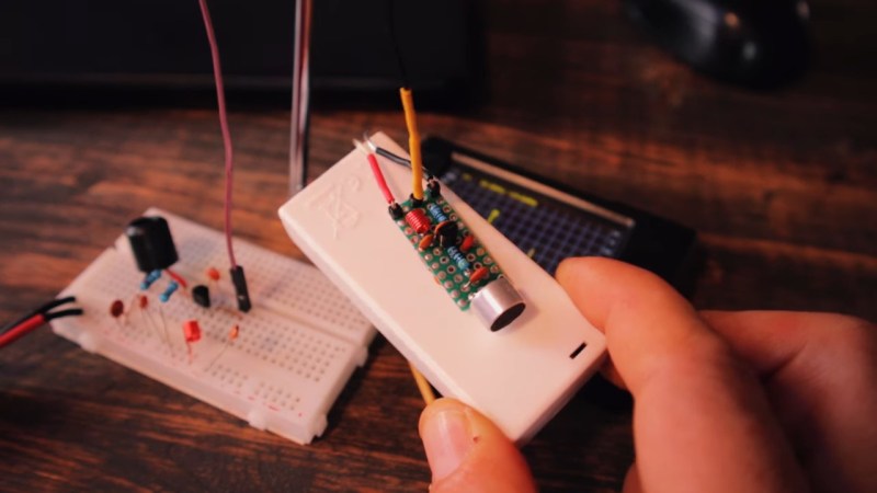
Luckily, you won’t need too many parts to recreate [Ciprian (YO6DXE)]’s project, most of which could be found in a decently stocked junk bin, or even harvested from e-waste. On the downside, the circuit is pretty fussy, with even minor component value changes causing a major change in center frequency. [Ciprian] had to do a lot of fiddling to get the frequency in the FM band, particularly with the inductor in the LC tank circuit. Even dropping battery voltage shifted the frequency significantly, which required a zener diode to address.
[Ciprian] ran a few tests and managed to get solid copy out to 80 meters range, which is pretty impressive for such a limited circuit. The harmonics, which extend up into the ham bands and possibly beyond, are a bit of a problem; while those could be addressed with a low-pass filter, in practical terms, the power of this little fellow is probably low enough to keep you from getting into serious trouble. Still, it’s best not to push your luck.
While you’re trying your hand at one-transistor circuits, you might want to try [Ciprian]’s one-transistor CW transceiver next.


This was the first electronics project I ever did as a kid. So nice to see it pop back up nearly 35 years on.
Same here…
Finally led to a ham license and a good job in RF-business.
Everything done right.
May I ask what kind of a job? Did you go to college too?
i still have the matchbox somewhere with my version, powered from a single AA. from a distance undistinguished from a normal one.
These are fun little circuits but “tiny”?
Heck, I was building FM bugs “ugly style” that were less than half that size 35 years ago
Wonder just how small it could be made with SMD parts… (Adds yet another project that will never be completed to the list)
Hi, I think the biggest part was or is the battery (button cell).
Also, I’d imagine using field-effect transistors probably was a thing in the 70s/80s, too.
In some places using tunnel diodes was a thing, here is the FM ( and part time AM) transmitter I put together as a child . This led to a degree in physics and a good job in microwave business too :-)
https://irls-narod-ru.translate.goog/per/bug11.htm?_x_tr_sl=ru&_x_tr_tl=en&_x_tr_hl=en&_x_tr_pto=wapp
I came up with the ‘Mark 2’ version. This one uses a 13.5MHz crystal from a broken Sony Vaio NFC module, and also does stereo as well. Small enough to fit inside a headphone jack with a 3mm stub sticking out.
It is slightly more complicated but doesn’t need a battery as draws power from the headphone output.
Where! Sounds cool!
I also want to see this
That’s interesting, have you published the circuit?
Tradecraft is one word.
Are you kidding me???
A Zener diode directly parallel to the batteries?
That’s a recipe to turn most of the battery charge into heat as quickly as possible, provided thaht the Zener survives the ordeal…
“Also place a 270 Ohm resistor before the Zener diode on the positive coming from the battery. I didn’t had that one in the schematic I used in the video.”
It’s in the video description…oops
Tried to use these in some theatrical productions many decades ago, the problem with these little transmitters is frequency drift.
Lots of things in the circuit will cause the frequency to drift, such as thermal drift over time, which will make the receiver go in and out of lock and you keep having to adjust the frequency on the receiver to compensate. And of course you don’t know whether the frequency drifted up or down.
Modern transmitters/receivers have crystal locked frequencies that don’t wander, and are more reliable.
(Not a comment on the project, only pointing out that the end result is almost unuseable.)
Remember when we just banged away on gpio pins for FM transmission? Good times
https://hackaday.com/2014/06/15/easily-turn-your-raspberry-pi-into-an-fm-transmitter/
It worked, I tried (star wars demo wav), but audio quality wasn’t that great.
Also, it needed RF filters so badly. Which made it unusable for real projects, unless some extra work had been spent.
Because a real radio transmitter (2 way radio etc) was more powerful and cleaner right from the start.
I remember doing one of these, except it had a variable capacitor so you could tune it the frequency a bit to a frequency not in use…
Back in the ’70s, we used to take the transmitter from a “Mr. Microphone” and add an output transistor to it. It boosted the power and decreased the body capacitance effects on the frequency.