You think of op amps as amplifiers because, no kidding, it is right in the name. But just like some people say, “you could do that with a 555,” [Doctor Volt] might say, “you can do that with an op amp.” In a recent video, you can see below, he looks at simulations and breadboards for five applications that aren’t traditional amplifiers.
Of course, you can split hairs. A comparator is sort of an amplifier with some very specific parameters, but it isn’t an amplifier in the classic sense.
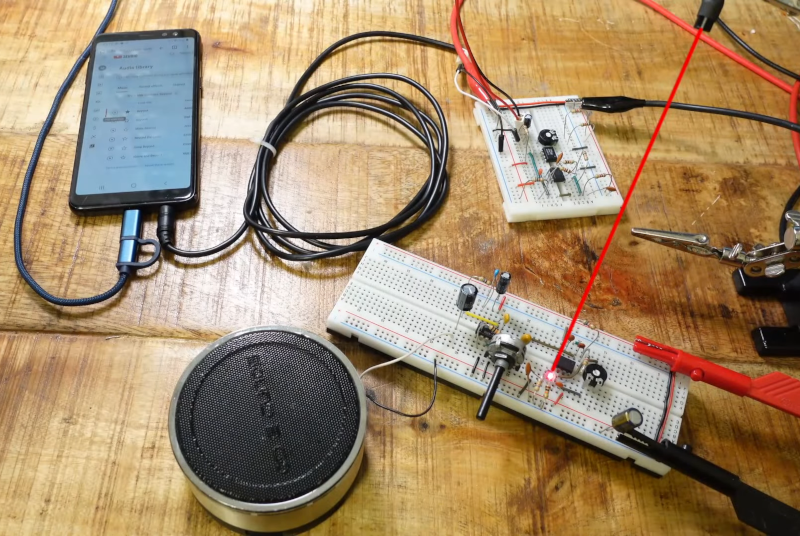
In addition to comparators, there’s a flip flop, a few oscillators, and a PWM audio over optical transmitter and receiver. If you want to test your understanding of op amps, you can try to analyze the different circuits to see if you can explain how they work.
Op amps are amazing for analog design since you don’t have to build up high-quality amplifier blocks from discrete devices. Even the worst op amp you can buy is probably better than something you have the patience to design in a few minutes with a FET or a bipolar device. Fair to say that we do enjoy these oddball op amp circuits.


A clue to why op amps aren’t simply a traditional amplifier (and never have been) can be found in their name, which is “operational amplifier”.
“A comparator is sort of an amplifier with some very specific parameters”
Yes, and a very standard op-amp circuit. As are flip-flops, Schmitt-Triggers.
Is it good to show this to people and remind them that stuff can be pretty simple? Yes. And people should really look at the circuits and try to understand them. It’s been a while for me as well (2nd year EE, I think).
On paper at arms length and squinting, a comparator might look like an op-amp, but woe betide you if you try to sub one in for the other in a real circuit and expect the desired performance (unless your expectations are low). Saturation recovery is a big difference, among other parameters.
There is nothing “odd” about these circuits. They’re all pretty common opamp applications.
But a word of caution about the schmitt trigger. This circuit can not be understood if you make the common but false assumption that “an opamp tries to make it’s inputs equal to each other”.
A much better way to analyze opamp circuits, is to look at what an opamp actually does. It takes the difference between the two inputs, and amplifies that with a big number. (approx 100.000 is common). Next step is to take another specification of an opamp, and that is the maximum rate at which the output can change, this is called the “slew rate”.
Combine these two, and you get: When the non inverting input is higher then the inverting input, the output goes up at the rate of the slew rate, if the inverting input is higher, then the output goes down with the slew rate.
This analysis always works because it simply is what opamps do. It also helps with analyzing when there is for example a BJT at it’s output, which in some configurations “inverts” how an opamp works. The opamp itself does not know anything about the external circuitry. It just has it’s inputs and output (And it’s power supply, possible compensation nodes and other details that are not significant to understanding the basics of a circuit).
Excellent summary. Short ,detailed and easily understood.
It’s true that it’s false about an op-amp in isolation. It’s misleading, and arguably false, that it’s false about circuit with an op-amp in negative feedback configuration.
It’s still false, but can be useful as a first approximation. You can run into major problems trying to treat negative feedback circuits as true “make the inputs equal” systems though.
First of all, the math breaks. An open-loop circuit with gain of 1e6 that produces 1V of output for Vpos-Vneg=1uV of input makes sense. So does a negative feedback circuit that naturally seeks the point where Vpos-Vneg=1/1+gain times the output. Trying to think in terms of Vpos-Vneg=0 makes you try to do all sorts of things that just don’t work.
Barrie Gilbert (one of the big 20th century analog designers.. invented the multiplier circuit still used in most radios) wrote an article about why the standard assumptions for an ideal op amp — infinite input impedance, infinite gain, and infinite frequency response — fall apart when you really start thinking about them.. a device that actually did those things would be almost useless:
https://www.edn.com/op-amp-myths-by-barrie-gilbert/
I like this explanation a lot :)
Silliest op-amp circuit I’ve done: An oscillator and driver solely to drive a capacitor-isolated voltage doubler, to power a digital panel meter that needed to be isolated. One-chip, $0.40 solution and I had it on hand, saved the $3 +1 day solution to get a ‘real’ one from Digikey. 15 years later, it’s still running.
My favorite “odd Op Amp circuit” Is the simple frequency discriminator.
Don’t try this with a FET input op amp it won’t work. This only works with bipolar transistor front end op amps. Where I use to work we built a transmitter (FM) that used an RCA CA748 op amp as a frequency discriminator. The key to making this work was the parallel tuned circuit across the inverting and non inverting inputs. The circuit worked well into the lower UHF range.
We had a line of transmitters that used this circuit for frequency control in our frequency locked loop transmitters, we also had a linear version that would generate a voltage proportional to the frequency. We used this provide reverse bias for a VCO for an L-band 100 channel FM transmitter.
The transmitters wee modulated by using a varactor diode in that parallel tuned circuit I mentioned above.
This was the preferred method of modulation although we did build transmitters that modulated by other means.
I miss the days when the strange and weird things could be found in microwave circuits; now it’s just nameless, and faceless black silicon dots with stubs and combs and striplines….
Thank you Conic Data Systems for the memories….
Where’s Tom Cat???
Good old Conic.
Scrapped a ton of their stuff into useful parts (lol) when I was growing up in San Diego in the 80s and 90s.
Tons!
There was a lot of good parts to be had.
Back in those days if you worked on the production floor you had access to a lot of free stock parts for some of your own projects…. (nobody abused it)
I left there for more money, and went to work in the two way radio business….
There are times I regretted it….
All it took was the six dollar per pay difference and the regrets vanished.
I did manage to buy one of the transmitters I worked on back in the day.
Found it on Ebay for about 2 percent of it’s original cost.
now I have a working S-band transmitter (2277.0MHZ for $45.00 USD. Makes a nice paperweight. :)
Any pictures to share? I am especially interested in the opamp circuit you described to understand for how that works.
I have a few but they are not on the web.
I have a few pieces from the era, prototype stuff and old limiter and discriminator boards.
The way the system worked is like this…..
A crystal that resonates in the 125MHZ range is multiplied and mixed with a VCO running at on half the output frequency. A harmonic of that crystal is mixed with the VCO to give us an IF of say 28.125MHZ. The IF signal is amplified in a limiter circuit, then fed to the discriminator. Just like in your Dad’s FM Hi-Fi rig the discriminator generates an error voltage when the VCO is not on frequency. That voltage kept within close boundaries due to the tendency for the circuit to “false lock”. This is not a big problem and is easy to deal with at the production level as every VCO is a little different. (hand built by good looking assemblers) To modulate this transmitter we put a varicap in the discriminator tank circuit and apply a little mod and the VCO is forced to track the discriminator’s excursions in resonant frequency. Oh by the way…..There is a Second Varacap diode in the discriminator to apply tempriture compensation to keep the transmitter on frequency Typical over -30 to +75C Although we did many, many transmitters that went down to -70C.
This design works well for low speed data and video, it is flawed in several ways.
First harmonics of the IF frequency mix with the multiplied crystal oscillator output. This will produce spurious signals in the transmitter’s modulation passband. The only to fix this is to shift the IF a few dozen KHZ. The other main issue is noise…. As the frequency locked loop approaches the output frequency the loop gain goes up, at the exact frequency the transmitter is suppose to be on the loop gain must be infinity. What ends up happening is the transmitter wonders around typically on one of our standard products tyis wondering was about 200 HZ second drift, random wondering about the center frequency. This turned out to be a big issue if you are using a PM and not an FM receiver. One of our customers make this mistake and ordered 175 of our 5 channel transmitters which they gave back to us and gave us some more money to design a PM version our transmitters. (already in R and D at that time) I managed to get this wondering down to 50HZ in some transmitters I did for a company supplying border surveillance gear to Israel.
That transmitter had tight specs for spurious emissions -90DBC, and to make things miserable for me three channels that the customer fell in the danger zone for that spur problem i mentioned above. I had REQUESTED IN WRITING to have those channel crystal frequencies changed due to that problem.
Well….
I made them buy new crystals, added a mod to shift the transmitter IF on those channels and the transmitter worked like a million dollars.
It did cause enough havoc having to change the crystals I received a visit from the Founder of the company who was still working as the VP for this division of Loral corp.
In the end I managed to bring about an important change to how those transmitters were built, however too little too late. Thanks to new modulation techniques and new parts on the approved parts list the phase mod transmitter design went forward and a better product was produced.
A short list of Conic Corp. accomplishments;
First all solid state 2500W S-band power amplifier covering the whole S-band.
First 100 and 200 channel synthesized L-band telemetry transmitters.
First 105 channel synthesized L-band transmitter.
We spent a few decades building telemetry transmitters for the Trident missle program. These transmitters were used during missile tests to show how well our stuff worked. I would point out during the seven plus years I worked there only one of these transmitters ever failed during a test.
Like many companies of that time who were pushing the state of the art; the hacker spirit lived. Although overcoming the inertia of the engineering department can be a challenge (they hate change especially when it’s not their idea) I did have an ally in the engineering department, thanks TomCat.
By the way the above mentioned part was a 5 transistor array which we used, my mistake.
The actual op amp used was a CA748. You could do some cool stuff with that part.
Long time since 1981 when I first started working there.
*Operational amplifiers
Operational amplifiers (op amps) are analog circuit blocks that take a differential voltage input and produce a single-ended voltage output
^
Check National Semi AN-32 here. From 1970. http://bitsavers.informatik.uni-stuttgart.de/components/national/_dataBooks/1973_National_Linear_Applications.pdf
heh it’s a couple years ago now that i realized an op amp and a comparator are the same thing
Except when you try to make one act like the other… They really are different things, with performance criteria optimized for the intended use. OK for demonstration and low-speed, low-performance projects, but otherwise poor substitutes for each other.
You’re close.. they’re the same core circuit — a differential amplifier — tuned in opposite directions.
Op amps are tuned to operate in the middle of their output range. They tend to get laggy and unresponsive if their output gets too close to either limit. They’re tuned to be slow, which gives them the flexibility to have reasonably linear gain. Most jellybean op amps you’ll see mentioned here at Hackaday have gain-bandwidth products between 1MHz and 10MHz, meaning their DC gain starts in the millions, but drops to 1 by the time your input frequency gets into the low megahertz range. They’re also designed to work well with their positive and negative input voltages almost equal.
Comparators are tuned to keep the output at one rail or the other. A comparator whose output is somewhere between the rails is an unhappy device. They’re tuned to be fast. Even an old design like the LM311 is spec’d to respond in 100ns. And they hate having their inputs nearly the same voltage. Most datasheets will have a note saying you need at least 100mV of differential voltage to get the fastest response times.
If you want to detect small voltage differences, you make what’s known as a precision comparator: run the inputs through an op amp for gain (usually with opposing diodes for feedback so the output never goes more than about 0.6V away from the input), then feed the output of that to a comparator. The op amp won’t take too long to produce a 100mV difference (100ns with a slew rate of 1V/us), and the comparator will take over from there.
thank you! your comment actually helped me understand in a little more detail
OK, this one is pretty odd too. Check out this tongue in cheek circuit from a couple of die-hard analog guys.
https://youtu.be/VXwOHzddzi8?si=dS0O6R6mnXJqbO_5
The credits are awesome :-)
https://hackaday.io/project/191222-op-amp-logic watch the linked video
Highly recommend Jung’s IC Op Amp Cookbook. Thick tome of solutions and explanations of how they work.