Although the CRT has largely disappeared from our everyday lives, there was a decades-long timeframe when this was effectively the only display available. It’s an analog display for an analog world, and now that almost everything electronic is digital, these amazing pieces of technology are largely relegated to retro gaming and a few other niche uses. [Maurycy] has a unique CRT that’s small enough to fit in a handheld television, but since there aren’t analog TV stations anymore, he decided to build his own with nothing but an 8-bit microcontroller and a few other small parts.
The rapidly-improving speed and versatility of digital computers has mostly driven analogue computers out of use in modern systems, as has the relative difficulty of programming an analogue computer. There is a kind of art, though, in weaving together a series of op-amps to perform mathematical calculations; between this, a historical interest in the machines, and their rarity value, it’s no wonder that new analogue computers are being designed even now, such as [Markus Bindhammer]’s system.
The computer is built around a combined circuit board and patch panel, based on the designs included in three papers in a online library of analogue computer references. The housing around the patch panel took design cues from the Polish AKAT-1 analogue computer, including the two dial voltage indicators and an oscilloscope display, in this case an inexpensive DSO-138. The patch panel uses banana connectors and the jumper wires use stackable connectors, so several wires can be connected to the same socket.
The computer itself has a summing amplifier circuit, a multiplier circuit, an integrator, and square, triangle, and sine wave generators. This simple set of tools is enough to simulate both simple and complex math; for example, [Markus] squared five volts with the multiplier, resulting in 2.5 volts (the multiplier divides the result by ten). A more advanced example is a leaky-integrator model of a neuron, which simulates a differential equation.
Even though digital cameras have lowered the barrier of entry to photography dramatically, as well as made it much easier for professionals and amateurs alike to capture stunning images without the burden of developing film, the technology behind them is considerably more complex than their analog counterparts. In fact, an analog film camera (not counting the lens) can be as simple as a lightproof box and a way to activate a shutter. Knowing that, any kind of film camera could be built for any number of applications, like this 3D-printed panoramic camera from [Denis Aminev].
The custom-built camera works by taking a standard roll of 35mm film, which is standardized to take 36 pictures, and exposing a wider section of the film to create a panorama. This reduces the number of pictures on the roll to 19. This is the fifth version of this camera, called the Infidex 176 V, and has everything a standard film camera would have, from an exposure counter, pressure plate for the film, a winder, interchangable lenses, a viewfinder, and a tripod mounting point. It does take a bit of work to assemble, as shown in the video linked below, but the final result is impressive and delivers a custom finished product not easily found or reproducible in off-the-shelf cameras.
The path to creating this camera was interesting as well, as [Denis]’s first custom film camera was a pinhole camera. From there he moved on to disassembling an SLR camera and attempting to reproduce all of its parts with 3D printed ones. With that in hand, he was able to modify this design into this panoramic camera which he likes because it reproduces the feel of widescreen movies. Although this camera reproduces all of the bells and whistles of a high quality analog camera, not all of these features are strictly necessary for taking pictures on film. Have a look at this minimum viable camera as well.
Ham radio operators may be familiar with slow-scan television (SSTV) where an image is sent out over the airwaves to be received, decoded, and displayed on a computer monitor by other radio operators. It’s a niche mode that isn’t as popular as modern digital modes like FT8, but it still has its proponents. SSTV isn’t only confined to the radio, though. [BLANCHARD Jordan] used this encoding method to store digital images on a cassette tape in a custom-built tape deck for future playback and viewing.
The self-contained device first uses an ESP32 and its associated camera module to take a picture, with a screen that shows the current view of the camera as the picture is being taken. In this way it’s fairly similar to any semi-modern digital camera. From there, though, it starts to diverge from a typical digital camera. The digital image is converted first to analog and then stored as audio on a standard cassette tape, which is included in the module in lieu of something like an SD card.
To view the saved images, the tape is played back and the audio signal captured by an RP2040. It employs a number of methods to ensure that the reconstructed image is faithful to the original, but the final image displays the classic SSTV look that these images tend to have as a result of the analog media. As a bonus feature, the camera can use a serial connection to another computer to offload this final processing step.
Although it can be hard to imagine in today’s semiconductor-powered, digital world, there was electrical technology around before the widespread adoption of the transistor in the latter half of the 1900s that could do more than provide lighting. People figured out clever ways to send information around analog systems, whether that was a telegraph or a telephone. These systems are almost completely obsolete these days thanks to digital technology, leaving a large number of rotary phones and other communications systems relegated to the dustbin of history. [Attoparsec] brought a few of these old machines back to life anyway, setting up a local intercom system with technology faithful to this pre-digital era.
These phones date well before the rotary phone that some of us may be familiar with, to a time where landline phones had batteries installed in them to provide current to the analog voice circuit. A transformer isolated the DC out of the line and amplified the voice signal. A generator was included in parallel which, when operated by hand, could ring the other phones on the line. The challenge to this build was keeping everything period-appropriate, with a few compromises made for the batteries which are D-cell batteries with a recreation case. [Attoparsec] even found cloth wiring meant for guitars to keep the insides looking like they’re still 100 years old. Beyond that, a few plastic parts needed to be fabricated to make sure the circuit was working properly, but for a relatively simple machine the repairs were relatively straightforward.
The other key to getting an intercom set up in a house is exterior to the phones themselves. There needs to be some sort of wiring connecting the phones, and [Attoparsec] had a number of existing phone wiring options already available in his house. He only needed to run a few extra wires to get the phones located in his preferred spots. After everything is hooked up, the phones work just as they would have when they were new, although their actual utility is limited by the availability of things like smartphones. But, if you have enough of these antiques, you can always build your own analog phone network from the ground up to support them all.
One of the major difficulties in studying electricity, especially when compared to many other physical phenomena, is that it cannot be observed directly by human senses. We can manipulate it to perform various tasks and see its effects indirectly, like the ionized channels formed during lightning strikes or the resistive heating of objects, but its underlying behavior is largely hidden from view. Even mathematical descriptions can quickly become complex and counter-intuitive, obscured behind layers of math and theory. Still, [lcamtuf] has made some strides in demystifying aspects of electricity in this introduction to analog filters.
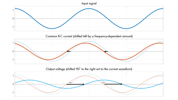
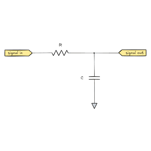
The discussion on analog filters looks at a few straightforward examples first. Starting with an resistor-capacitor (RC) filter, [lcamtuf] explains it by breaking its behavior down into steps of how the circuit behaves over time. Starting with a DC source and no load, and then removing the resistor to show just the behavior of a capacitor, shows the basics of this circuit from various perspectives. From there it moves into how it behaves when exposed to a sine wave instead of a DC source, which is key to understanding its behavior in arbitrary analog environments such as those involved in audio applications.
There’s some math underlying all of these explanations, of course, but it’s not overwhelming like a third-year electrical engineering course might be. For anyone looking to get into signal processing or even just building a really nice set of speakers for their home theater, this is an excellent primer. We’ve seen some other demonstrations of filtering data as well, like this one which demonstrates basic filtering using a microcontroller.
[Tim] noticed recently that a large number of projects recreating discrete logic tend to do so with technology around 70 years old like resistor-transistor logic (RTL) or diode-transistor logic (DTL). To build something with these logic families nowadays requires an intense treasure hunt of antique components bordering on impossible and/or expensive. Rather than going down this rabbit hole he decided to invent a somewhat new logic system using analog components in this entry in our Component Abuse Challenge.
The component in question here is an analog multiplexer, which is normally used to select one of two (or several) signal lines and pass them through to an output. Unlike digital multiplexers which only pass 1s and 0s, analog multiplexers can pass analog signals since the transistors aren’t driven to saturation. He has come up with an entire system of logic gates using these components, with trickier devices like latches eventually implemented with help from a capacitor.
The first attempt at using this logic system had a small mistake in it which caused these latches to behave as oscillators instead, due to a polarity mistake. But a second attempt with simplified design and reduced component count ended up working, proving out [Tim]’s concept. Not only that but his second prototype is functioning at an impressive 15 MHz, with a possibility of an even higher clock speed in future designs. Not bad!