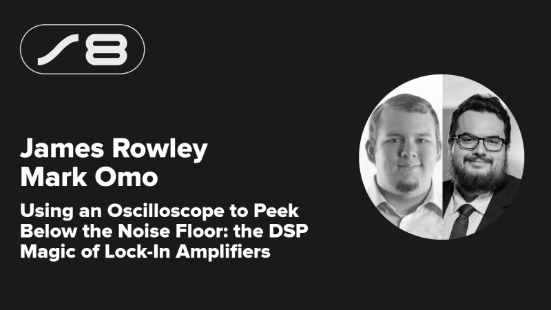
When you’re hunting for a signal with your oscilloscope, the stronger it is, the better. If it’s weak, you might struggle to tease it out from other interference, or even from the noise floor itself. You might wish that you were looking for something more obvious rather than the electromagnetic equivalent of a needle in a haystack.
Finding hidden signals below the noise floor may be a challenge, but it needn’t be an insurmountable one. James Rowley and Mark Omo came to the 2024 Hackaday Superconference to tell us how to achieve this with the magic of lock-in amplifiers.
Noise
As James explains, you can do lock-in amplification with just about any analog-to-digital converter and DSP that you might have on hand. For example, the oscilloscope you already have in your workshop. “The magic of this technique is taking a noisy signal, just rejecting all the noise, and getting just the part you want—just the signal you’re interested in,” James explains. “It is a very powerful technique for measuring how a signal flows through a system.”
“A lock-in amplifier is a great way… to lock in to those very small signals that can be swamped out by noise and interference, and actually measure signals that are well below the noise floor with a negative signal-to-noise ratio,” says James. “Essentially, what a lock-in amplifier is, is an ultra-narrow bandpass filter.”
In the talk, James uses a simple analogy to explain how this works. He asks the audience to imagine a speaker and a microphone. In this analogy, ideally, the microphone picks up whatever noise the speaker is putting out, but in the real world, there are lots of other noise sources from the environment that can swamp the signal from the speaker itself. However, a lock-in amplifier would be able to reject that other noise, locking in on just the sound from the speaker itself. Lock-in amplifiers apply to all sorts of applications, from picking up extremely sensitive signals from load-cells, to measuring very high or low electrical resistances, and even finding locations of heart catheters during delicate medical operations. Wherever there are tiny important signals that need to be picked up, lock-in amplifiers can probably help.
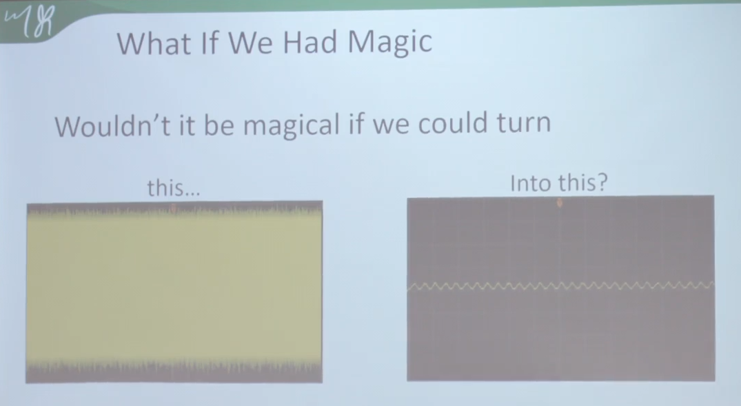
Mark then walks us through the DSP magic required to actually find signals beneath the noise floor. He explains that by heavily filtering out noise outside the area of interest, it’s possible to effectively increase the signal-to-noise ratio and pick up the desired signal even if it’s quite faint. Traditional filters aren’t quite good enough to reduce the noise by the required amount of 300 times or so, so alternative solutions are needed. To do lock-in amplification, the measured signal is first shifted down to zero hertz, and averaged out over time. It sounds a little funky, but Mark explains the trigonometry and associated math to make it all work for a signal of any given bandwidth. Importantly, though, this technique also needs a reference signal to work, so the amplifier can effectively lock-in on the signal you’re actually looking for.
The talk then covers the practical—how to build a lock-in amplifier with real hardware. Commercial off-the-shelf options exist, or you could go the discrete analog route—but both are expensive and fussy. Alternatively, you can just use an analog-to-digital converter. “Like the one in your oscilloscope!” notes Mark. He explains how this is set up and how it compares to traditional approaches; basically, it’s more accessible, if not quite as high-performance. You basically end up using one channel as a reference input, while the other channel is hooked up to the signal you’re actually trying to find.
The better the ADC in your oscilloscope, the better it will perform—better bit depth, buffer depth, and sampling rates are all advantageous in this regard. You’re limited by quantization noise and the fact the oscilloscope may not have a particularly low-noise front end, and how much you can average the signal with the oscilloscope’s memory depth, but it’s a workable way to get started with a lock-in amplification setup. As a guide, something like a Rigol DS1054Z has enough memory depth to achieve a 1700x reduction in noise, which helps a great deal when hunting for a signal beneath the typical noise floor. Code to achieve this is available on Github for the curious.
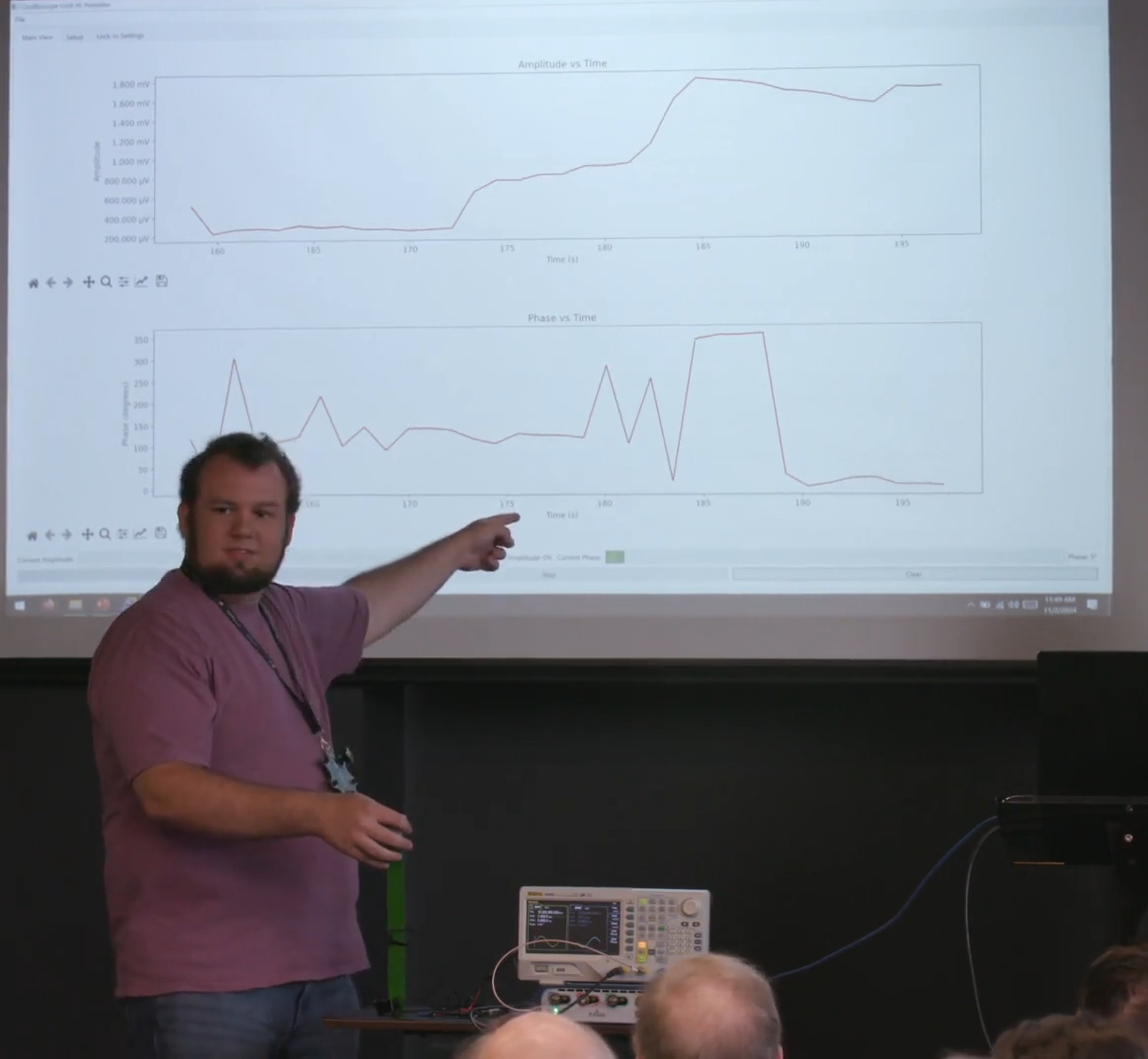
The talk wraps up with a neat demonstration. A microphone and speaker are set up at a set distance of 8.5 cm, at which point the signal should show a 90-degree change in phase based on the signal being fed through the system. Mark and James show how their system is able to accurately measure the phase shift in the desired signal even in a loud room with a full crowd applauding while the demo runs.
If you regularly find yourself struggling to measure dim signals that you know are there, somewhere, you might find these techniques highly useful. This talk serves as a great primer for this very useful DSP technique.


Please stop repeating the “signals below the noise floor” line. It is impossible to reconstruct a signal that’s actually below the noise floor. The microphone analogy explains this quite nicely: The signal only looks drowned if you look at the noise across the whole channel bandwidth. But that’s not what you’re doing when you apply a filter. The bandwidth you’re looking at is now much smaller than the whole channel, because you know where to look and what energy levels to reject. The signal-to-noise ratio suddenly gets much better not because there’s some magic involved, but because he initial perspective was wrong.
It’s the same with RF modulations that are regularly claimed to be below the noise floor ( e.g. GPS, WSPR etc.). When you look at the actual bandwidths used, the signal of course has to be at least several times stronger than the noise to still be decodeable.
That’s all technically correct (and I agree with the outrage), but it doesn’t describe the (common) case where the signal is spread over a channel that’s’ much wider than the actual information bandwidth, as is the case in GPS signals and many other modulation schemes.
In the specific case of GPS, the signal occupies a bandwidth of ca. 22 MHz, with all that noise bandwidth, even though the actual information rate is only 50 bits per second. By using a relatively huge bandwidth, the lock-in process can get a nanosecond-accurate estimate of the signal phase and thereby the time of arrival.
You couldn’t estimate the phase that accurately if you were just detecting the dozens of Hz wide “signal” bandwidth.
The noise in the channel, though, comes from the whole 22 MHz, and the signal very much is dozens of dB below that noise power. You could not receive the signal without receiving all that noise too.
In that sense, it’s correct to say the signal is below the noise.
I understand what you’re saying.
AND, if you were broadcasting a signal on 915 MHz, would you measure the noise on 2.4 GHz? Of course not. You measure the noise at the frequency of the signal.
How about if someone was ALSO broadcasting the same signal on 5.8 GHz? Would you measure the noise across 5.8 GHz – 915 MHz = 4.9 GHz? (Clearly not – that makes no sense at all).
Importantly, the frequency of the signal, not the frequency of a carrier that someone earlier multiplied with the signal. (Or several such carriers). And most certainly when it’s broadcast on multiple carriers, subtracting the frequencies of the carriers makes no sense at all. Yet …
While it’s obvious that a signal on 915 MHz and 5.8 GHz isn’t a 4.9 GHz signal, sometimes our brains get silly if the two carriers are closer together. They are two separate, unrelated carriers if they on 915 and 2400; they are two separate unrelated carriers if they are on 915 and 1200. They’re still two separate carriers if they at 915 Mhz and 1110 Mhz. Or 915 MHz and 918 Mhz.
A signal on 915 MHz and on 918 MHz isn’t a 3 MHz wide signal. No more than 915 and 5800 makes a 4900 MHz wide signal.
It’s two different carriers, each carrying a signal of maybe 100 Khz width or whatever.
… And so the relevant noise at the noise at that specific frequency.
Not everything in between the two separate frequencies.
And a tip: If you have a repetitive signal (as generally required by this process) and can get a reliable trigger synchronous to it, you can simplify the process by just telling your ‘scope to collect many averages.
This only works well if you have a decent scope that uses enough bits for the averaging arithmetic. Unfortunately the Rigol 1054Z (and its ilk) is broken in that respect, and is useful for only a few averages.
So this is like a direct conversion receiver, but using an oscilloscope?
Sure, more or less. A direct conversion receiver could be considered a type (or part) of a lock-in amplifier, especially if it includes a reference clock and is followed by a DSP.