The choice between hardware and software for electronics projects is generally a straighforward one. For simple tasks we might build dedicated hardware circuits out of discrete components for reliability and low cost, but for more complex tasks it could be easier and cheaper to program a general purpose microcontroller than to build the equivalent circuit in hardware. Every now and then we’ll see a project that blurs the lines between these two choices like this Pong game built entirely out of discrete components.
The project begins with a somewhat low-quality image of the original Pong circuit found online, which [atkelar] used to model the circuit in KiCad. Because the image wasn’t the highest resolution some guesses needed to be made, but it was enough to eventually produce a PCB and bill of material. From there [atkelar] could start piecing the circuit together, starting with the clock and eventually working through all the other components of the game, troubleshooting as he went. There were of course a few bugs to work out, as with any hardware project of this complexity, but in the end the bugs in the first PCB were found and used to create a second PCB with the issues solved.
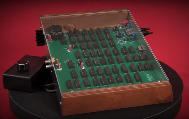
With a wood, and metal case rounding out the build to showcase the circuit, nothing is left but to plug this in to a monitor and start playing this recreation of the first mass-produced video game ever made. Pong is a fairly popular build since, at least compared to modern games, it’s simple enough to build completely in hardware. This version from a few years ago goes even beyond [atkelar]’s integrated circuit design and instead built a recreation out of transistors and diodes directly.
Thanks to [irdc] for the tip!


Google “original pong schematic” and it comes right up.
I used “atari pong schematic”. It throws also a PDF with chips layout. Anyway this article is nice reminder of history.
Indeed, now it does – back when I started, all I found was that blurry picture and somebody else’s work which I decided not to use as I wanted to experience that fun part myself 😊
What is a “discrete” component, exactly? Where do you draw the line?
Ideally it should mean no ICs, Transistors at the most complex. Here I think they mean basic logic chips and nothing specialized/programmable
Yes, but it’s a jump to go from and/or/not to flip-flops and muxes/demuxes. Some “basic” 74xxx logic chips can have quite a bit of logic in them (like a 4-bit adder, 256-bit RAM, etc.)
I think same.
For my own purposes (as I do exercises like this from time to time :) ), thinking in tiers is reasonable:
– Single diodes, transistors, etc.
-> option: permit use of arrays to optimize layout/placement/BOM (if rationalization is needed, dual SOT363s are all* independent dice!)
– Single (or dual/quad, see above) op-amps, comparators, logic gates, etc.
– MSI: logic blocks such as flip-flops, decoders/muxes, registers, converters, etc.
– VLSI: purpose-made ASICs, or programmable
-> the challenge might then be to use it in an interesting way, evaluate hidden/undocumented features, optimize the code (in C, ASM, etc.) for various ends (minimum code space, maximum performance/samples/bits/etc., add features, add networking, etc…)
And of course we can extend further down the list, into hardware and programming toolchains and software stacks. Maybe you go out of your way to do something the hard way once (say, write a canvas from scratch, or RTOS, or file system, or..), to better understand what’s going on (and what’s wrong when it breaks!) in the standard/commercial equivalent. There is very much a meaningful, say, “discrete kernel from scratch” sort of project, that some people do for example!
Since these builds are almost all wildly beyond economic value, the didactic value is the focus. If one seeks to better understand 2nd-tier components, then building circuits with those components exploded as their 1st-tier equivalents, is an excellent way to develop that. And so on for each pairing of levels.
And, these are typically very individually focused projects: exceptions are easy to make. For example, my load dump generator ( https://hackaday.com/2024/10/13/building-an-automotive-load-dump-tester/ ) is of discrete design, but I allowed exceptions for the aux supply and trigger circuits, which weren’t the focus of the build; the power electronics, and its control, was. I could of course build out a power supply in a handful of transistors, or a one-shot timer instead of the 555 (indeed I have schematics on hand for these, give or take adaptations and testing, which is the hard part), but the core system at that point is perfectly usable, and these are conveniences, outside of the project core, that I’m perfectly happy to take a shortcut out of. And, given the scrounge-minded build, this still leaves a little work\\fun for someone else to do, if they don’t happen to have those components available. ;-)
Where are the discrete components gone? Long time passing.
Microcontrollers, every one
They’re still available, as far as I know.
741 op-amp, 555 timer, 386 amp, BC548 and 2N2222A transistors etc..
Can it play Doom, with a few added components ?
Could it play Doom ?
(with a few added components)
Discrete logic as in IC chips to do various AND/OR/XOR/NOT functions. “Discrete” as in not with a CPU or MCU. It can be implemented in transistors theoretically.
How to Design & Build Your Own Custom TV Games (Tab Books 1978)
I used to have this book. I still do, but I used to, too.
Gave away the dead tree version, but the ebook is here:
https://www.worldradiohistory.com/BOOKSHELF-ARH/Technology/TAB-Books/TAB-How-to-Design-and-Build-Your-Own-Custom-TV-Games.1978-Heiser.pdf
Wow that’s a real nice one… Makes me glad I now have Unity and Unreal installed!
Hi all, Not sure if relevant as just found this page.
I have original ping pong board, scematics and parts!!! I used to be the only UK person to repair these many years ago and even designed and made a conversion kit (sub board) to convert pong to breakout, before moved on to video game software, writing versions of space invaders and later for the arcade industry. Still have huge library of circuit drawings, boxes of circuit boards from the black and white era and thousands of ram, eprom and ttl logic hanging around. Anybody needs info feel free to reply or call me afternoons only on 07836 239 932 John Richards (used to be Competitive Video in Surbiton, Surrey.
That’s awesome, thanks for sharing !
Where are the board’s decoupling caps? I recommend 0.1uF a few dozen LOL
Hi, sometimes they’re underneath the ICs, in the middle of the sockets.
I built such a thing in 1974 using op amp integrators. Was fairly simple.
Lookup the schematics for the Magnavox Odyssey, It’s all done with discrete transistors and diodes
I couldn’t watch the video fully from start to end, but from what I skipped, it is very nice!
It’s clean, clear, neatly filmed, and the end product both works and is gorgeous!
Thank you for sharing, I will watch it fully latter = D
Atari’s Pong was not the original. I was given a tabletop “Table Tennis” machine in the late 70’s, ironically from the nearby tennis club. It had 3 massive circuit boards of discreet logic and they were clearly marked as having been assembled in February 1970, 2-1/2 years before Atari’s. It had a huge 21″ CRT mounted under a 1/2″ thick glass tabletop. The power supply alone weighed 40 lbs, the entire machine weighed 300. It’s unclear who made it, there was no clearly marked manufacturer name anywhere on it, not even on the schematics taped inside.
I quickly fixed it, just a blown fuse. My teenage friends and I played it well into the 80’s.
My dad worked for the company that made the original Pong in the 70s, it was actually his idea to make a “home” version of the cabinet that just had a pushbutton instead of the coin acceptor. We had one until the mid 90s when we moved to Oregon and dad gave it to my uncle for his man cave (No idea what became of it). Also still have the schematics somewhere!
Pong is a great starting point for a video circuit. The video out on my game console project started life as an implementation of Pong’s sync section, replacing the rest with an EEPROM.