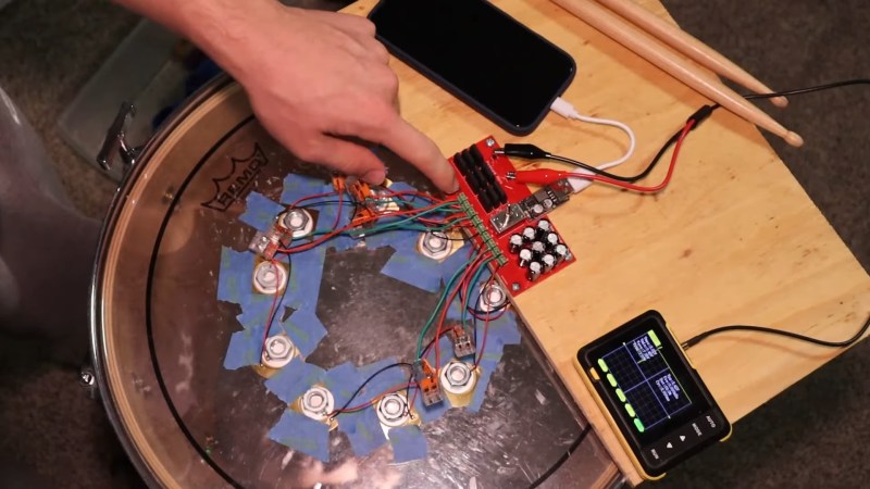
Drums! You hit them, and they vibrate. It’s kind of fun. Piezoelectric elements can create electric current when they vibrate. [Will Dana] put two and two together to try and charge his phone on his YouTube channel WillsBuilds embedded below.
It worked… about as well as you might expect. Which is to say: not very well. The random piezo elements [Will] glues to his drum almost certainly aren’t optimized for this use case. Adding weight helps, but it doesn’t look like a tuned system. Even if it was, piezoelectric generators aren’t terribly efficient by nature, and the (small) losses from the required bridge rectifiers aren’t helping. An energy-harvesting chip might have worked better, but it probably wouldn’t have worked well.
Since he cannot produce enough voltage in real time, [Will] opts to charge a capacitor bank that he can dump into the phone once it gets enough charge in it to register with the phone’s circuitry. It takes about 30 minutes drumming to charge the capacitors in parallel, before switching to series to get the voltage up to discharge. The capacitors drain in about a quarter second, probably to no measurable result– but the phone does read as “charging”, which was the goal.
Did it work? Technically, yes. The phone was “charging”. Is it practical? Certainly not. Is it a hack? Undeniably so.


Goofy clickbait for the hard of thinking, but I’ll bite.
Piezo elements can be fairly efficient, but it’s all about impedance matching: both mechanical and electrical.
That’s the purpose of that brass disk: it’s a mechanical impedance transformer from the extremely high impedance ceramic to the much lower impedance air. Think of it like a lever: a high force but short distance at one end (the ceramic at the middle) translates to a small force over a long distance (in air), with reasonable conservation of energy.
Same with the electric impedance. Electrically, a piezo element is a small, high voltage ceramic capacitor that produces pulses of charge when deformed. Trying to run that through a diode rectifier will lose much of that charge through the diode capacitance and recovery charge: Careful selection of a diode is needed, or an impedance transformer.
So, randomly sticking a bunch of elements on a drum head without considering the coupling (mechanical impedance matching) to the piezo likely won’t lead to success. (Even if glomming a few nutweights is a step in the right direction).
You’ll also need to ensure they are all mechanically and electrically in phase so the outputs will add up.
Likewise, putting a low impedance load (capacitors in parallel) to collect the charge won’t be the best way to harvest energy from the high impedance source.
It’s especially bad when rectified by a diode bridge like the one he used, which might be close to the worst type of diode to use due to its high capacitance, high leakage current and large recovery charge.
It’s too bad — engineered adequately this could actually work.
Oh, there are so many that are hard of thinking.
Thanks to Doug and the Slugs for introducing me to that turn of phrase.
Thanks for the response! This is Will, the guy who made the project. Factoring in impedance isn’t something I had thought of, and there are some super interesting factors at play here! Thanks for the info, as it lead me down a research rabbit hole to implement in future projects. I am curious, though, why does the impedance in the capacitor circuitry matter? The caps are connected to the output of the rectifiers, so wouldn’t they be charged with only DC current? I’m confused as to what role impedance plays in that part of the circuit.
-Will
Hey Will, sorry if that all came off a bit harsh. It’s just dismaying to see a great idea spoiled by taking a few wrong directions due to simple unawareness of key issues.
Piezo elements are high impedance: High voltage at low current. By putting a low-impedance load (the caps) on them, you might be collecting most of the charge (well, except for the considerable amount soaked up in the power rectifier recovery charge). But you’re losing all the power in that current (or energy in that charge) because you’re damping it by the low impedance load. Energy in a cap is 0.5CV^2. That V^2 term is important! You don’t want to leave all that voltage on the table.
To learn more, study datasheets and application notes for devices specifically designed for piezoelectric energy harvesting, like the LTC3588
I tried using a piezo disc that was a tweeter as an under the bridge pickup for my steel guitar. It worked fine it seemed under that triangle of wood pressed against the neck board. The feedback setup I was creating quit when I tuned down, and went up when I tuned up. I figured pressure on the wafer had something to do with it. Sure enough I pressed down on the bridge the tone went into fuller sound as if I dialed a low pass filter down to deeper bass. I figure the disc was operating in a more linear range.
I changed to an electret mic buried in the piece of wood and no pressure changes of tone or gain, full tone.
During the experiments with the disc pickup I could get at higher pressure enough actual power to hook up a speaker with no amp and hear sound at acoustic level not like a spruce sound board but sound none the less. A passive electric guitar! A search showed that there is a practice electric guitar with this setup and a switch for output or built in speaker with no battery.
So I see where the small mass on the discs come from. Try putting the discs into a practice pad with a mass backing it up. It should up things a bit, try a big cone speaker on it.
Did I catch something about charging gear from a soldiers boots? Maybe it didn’t work.
Could they be used to send signal to switch smart lamps on/off .