One part wants 3.3V logic. Another wants 5V. What do you do? Over on the [Playduino] YouTube channel, there’s a recent video running us through a not-so-recent concern: various approaches to level-shifting.
In the video, the specific voltage domains of 3.3 volts and 5 volts are given, but you can apply the same principles to other voltage domains, such as 1.8 volts, 2.5 volts, or nearly any two levels. Various approaches are discussed depending on whether you are interfacing 5 V to 3.3 V or 3.3 V to 5 V.
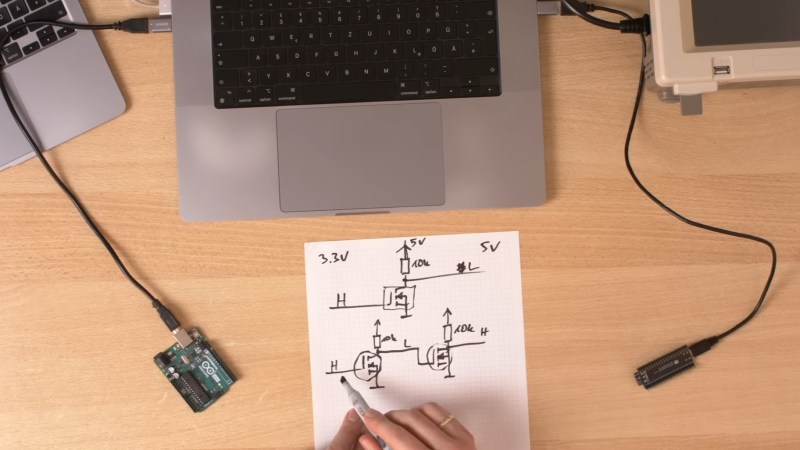
The first way to convert 5 V into 3.3 V is to use a voltage divider, made from two resistors. This is a balancing act: if the resistors are too small, the circuit wastes power; if they are too large, they inhibit fast signals.
The second approach to converting 5 V into 3.3 V is to use a bare resistor of at least 10K. This is a controversial approach, but it may work in your situation. The trick is to rely on the voltage drop across the series resistor to either drop enough voltage or limit the current flowing through input protection diodes, which will clamp the voltage but also burn out with too much current flow.
The third approach to converting 5 V into 3.3 V is to use chips from the 74AHC series or 74LVC series, such as inverting or non-inverting buffers. These chips can do the level shifting for you.
The easiest approach for going in the other direction is to simply connect them directly and hope you get lucky! Needless to say, this approach is fraught with peril.
The second approach for converting 3.3 V into 5 V is to make your own inverting or non-inverting buffer using, in this case, an N-channel Enhancement-mode MOSFET. Use one MOSFET for an inverting buffer and two MOSFETs for a non-inverting buffer. Just make sure you pick N-MOSFETs with 3.3 V or 5 V gate drive voltage VGS. Alternatively, you can use a buffer from the 74HCT series.
The video provides a myriad of approaches to level shifting, but you still have to decide. Do you have a favorite approach that wasn’t listed? Have you had good or bad luck with any of the approaches? Let us know in the comments! For more info on level shifting, including things to watch out for, check out When Your Level Shifter Is Too Smart To Function.


There is another version that is a bidirectional level shifter using a single mosfet. I have seen it quite a few places (sparkfun, raspi, etc) and I have successfully used it to level shift for my Pick and Place feeder adapter.
https://electronics.stackexchange.com/questions/555631/understanding-how-this-bi-directional-logic-level-shift-works
Thanks for the link. The same idea is expressed in the video I wrote about, see t=1024: https://youtu.be/4bitY6zHLP0?t=1024
Glad to see it was covered. I only read your description :)
It works really well if you get the BSS138 in a dual package and use r packs. You can make a 4 channel level shifter from 4 parts. (like I did here https://github.com/Ccecil/3v3-5v-LevelShifter ).
I stole the dual package idea from the “Arduino nano every” which I was tapping into the RX/TX lines on. They use this setup between the usb MCU and main MCU. Except they don’t use rpacks.
Thanks for the tip!
There are parts made specifically for this. See, e.g. NVT2002-2010.
Yes this circuit works like a charm. I’ve used it heaps to drive ws2811 LEDs from 3.3v ESPs.
Since I’m using it only in one direction to shift up, the voltage left hand resistor isn’t even needed.
Even in bi-directional mode you can usually drop the left hand resistor and turn on the internal pull-up on the pins you’re driving.
Where it doesn’t work is level-shifting some serial buses where one or both ends are expected to be tri-stated (up-down-floating). Sometimes these can be made to work by adding biasing resistors to “fake” it, but it depends on the device.
Zener diode! As long as going from higher to lower voltage. That’s a hack I’ve used in flashlight drivers like in the case of a tiny13 which wants absolutely no more than 6V, but with a supply of 2S/8.4V 18650s. Works fine on mechanical switch lights that physically break the circuit when off, not so great for momentary switch where power is applied 24/7.
lol. Okay. But maybe don’t put that one on your resume. :)
Well, thankfully I don’t need to deal with any more resume-related garbage for however much longer I’ll be around, but. If it doesn’t explode or burn up, and the single cell driver works reliably for years and years with 2S input & 6V LED, what’s the problem? It’s a hack. Is there some other definition of that word being used here?
What I was trying to say is: nice hack!
Oh… sorry, I have a bit of PTSD around this, since I honestly do not know how to do it ‘properly’, but still managed to find solutions.
On a different driver that happened to be a from-scratch design (and not a bodge of an existing part), I used an inductor in an apparently unconventional way. Some EE types on a different forum found the design and tore it a new one, because they could not comprehend that the inductor was being (mis)used as a choke (they are essentially the same thing, right?). I used a relatively big chonky SMD piece rated for something like 18 amps continuous, just from memory.
The problem the inductor/choke solved was that at the tiny13’s minimum PWM value of 1, the light was still much too bright. The inductor in series with the LEDs (six of them) calmed the min level way down, and didn’t affect the full output not even a little bit. Worked great. Inductor selection was by trial and error – 1.2uH cut it too much, 0.68 was juuuust right. Only added 2 more components to the prior board design.
Oh… OK… level shifting. I get it now.
Let’s just pretend I did that on purpose to add some extra layers to the ‘on another level’ thing.
As long as speed is not important, you can use resistive voltage dividers, opamps or whatever, but if you want both a decent speed, and keep it affordable then the “old” logic families are still interesting.
Some examples:
3V3 uC output to LS ttl IC has some extra beef for line driver (stepper motor optocouplers)
3V3 uC output to HCT logic for “general purpose 5V outputs.
With 5V to 3V3. I think the good old LS logic is mostly suitable, but you’d have to check the I/O levels. Some 10 to 30 years ago it was quite common to have some tables on hand for voltage levels of different logic families and in which ways they can be combined.
You can of course also use specifically designed “logic converter” IC’s. But they cost money and take up PCB space. If a circuit can be designed by using a few IC’s of some (old fashioned) logic family, then both the conversion and some extra function can often be done with one IC. (“bytewide” or shift register, etc).
“3V3 uC output to LS ttl IC …”
Using bipolar logic that way may have unwanted side effects. The 5V TTL input can source current via the upper output MOSFET into the 3.3V rail. Depending on the number of such level shifters, the 3.3V rail can be pulled above safe values. For higher output currents an ULN2003 is the better choice.
Open collector inverter or buffer, 74HC06 or 74HC07. 6 per package, use with pullup resistors.
I have to say it, fantastic title to this article.
lol, it’s great, isn’t it? I wish I could take credit but the editors came up with it!
A short paragraph on “this is better than using 2 power supplies because…” would be nice for the slow-witted among us such as myself who still has fond memories of the Radio Shack 9v plug-into-the-wall power supply.
Because it’s not the same? It’s assumed you will have two power supplies. But you need to convert the signal from one voltage level to another, ie your sensor talks in 5v while the mcu burns above 3.3
Perhaps you could use wires to connect the devices each to its appropriate power supply? Your answer doesn’t really sell it, i.e. doesn’t make me understand. I eat with a spoon. My TV, computer, and guitar amp all run on different voltages. What voltage does your notional sensor send its data to the thingamajig at? Do you understand that I don’t understand?
You should connect each device to the appropriate supply voltage, otherwise they might not work. The issue here is when you want the device that is connected to 5V and uses 5V push-pull CMOS logic to talk to the device that is connected to 3V and uses 3V logic. Having two different power supplies is the reason that there is a problem in the first place, not a solution to the problem.
From what you say it sounds like the problem is having two devices using different voltages. Still not helping me understand. If the voltage reducer goes between the higher voltage device and the lower voltage device, Sheet Nocturnal! That’s all you had to say! Of course then due to my not understanding, the question of what happens when the lower voltage device needs to send signal to the higher voltage device is not clear. I should take up dentistry because this is like pulling teeth. No offense.
Optocoupler to a pnp or npn transistor to gate a 5v supply, currently using this to dtive 24v circuit from 3.3v logic on a rpi pico.
in the rare case i’ve needed this, i’ve used a pull up resistor on the input, and either configure the output for open drain or use an NPN for the pull down (inverting, of course). Obviously, wastes some current fighting the pull-up. And there’s some caveats if you’re driving it fast, i’m sure. Kind of a braindead approach but i’m surprised it wasn’t mentioned in the write up.
If you need to deal with a wide voltage range, you can use an analog mux like the 4053 to switch between the output logic levels. Lauterbach used MAX4616 for the outputs of their v3 cables. For the inputs they used DS90C032 LVDS receivers where one pin of each comparator was fixed to the threshold voltage.