

However you make a digital computer, you need something to represent a binary digit. Usually this is some form of switch: a relay, a tube, or a transistor, although there have been other ways to represent state. In 1954, [Eiichi Goto] of Japan invented the parametron, a resonant circuit using a ferrite core and a capacitor that could be moved between two phases.
According to [Goto’s] 1959 paper, the device is effectively a parametric oscillator, similar to some used at UHF frequencies by hams. The idea is that a tuned circuit is set to some frequency and driven with twice that frequency.
A What?
A parametron is essentially a resonant circuit made with inductors or capacitors whose reactance is varied at twice its resonant frequency. That “pumping” causes the circuit to oscillate at half the pump frequency. The neat trick is that there are two equally stable oscillation states at half the pump frequency, separated from each other by 180° of phase. Those two phases become binary 0 and 1. Depending on the incoming signals, one phase will win over the others.
We normally think of logic levels as voltages, although sometimes we use current direction. The parametron does neither. The phase of the AC waveform determines if the state is a one or a zero.
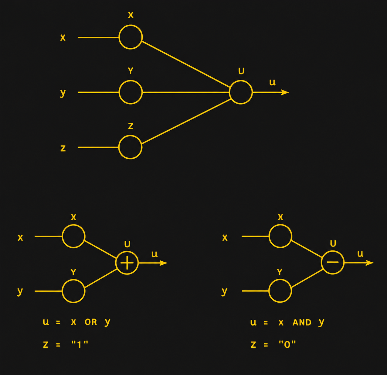
To make a logic gate, several preceding parametrons are weakly coupled into the next one. When that next stage is excited, the incoming signals provide a tiny initial oscillation. Because the parametron behaves rather like a regenerative amplifier, that initial signal rapidly grows into a full-amplitude oscillation. With three inputs, signals having one phase reinforce each other while opposite-phase signals cancel, so the new parametron naturally settles into the phase held by the majority of its inputs. Thus a three-input parametron is inherently a majority gate.
Ordinary Logic
Tie one input permanently to 0 or 1, and the same circuit becomes AND or OR; reverse the polarity of a coupling transformer and you get inversion. You can see this in the graphic from the original paper. In practical machines, groups of parametrons were driven by staggered clock phases so the result of one stage was established before the next stage was allowed to oscillate.
A chain of three parametrons can form a basic SR flip flop. [Goto’s] paper shows more complex forms and circuits like a parity checker. The catch, of course, is speed. Even a high-speed parametron topped out at about 6 MHz, and the clock frequency of a computer built with such devices would be down in the 140 kHz range. On the other hand, each parametron oscillates, and thus each gate regenerates a new output from its input signals, so a single output could easily drive 10 or 20 inputs.
In Practice
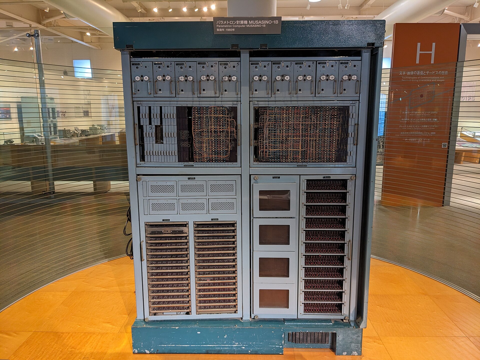
The largest of these computers had 1,024 words of core memory. What’s more, parametrons could drive magnetic cores differently than conventional core memory. One advantage is that, unlike conventional core memory systems, reading these cores did not erase them.
Aftermath
Of course, active devices had the speed edge, and parametrons faded into history. There were some other uses, including numerical control of machining devices, a Morse code to Teletype converter, and even a prototype system that used parametrons to sense cars passing over a road.
While it is just a footnote now in the history of computing, a significant number of Japanese computers used the technology. The Engineering and Technology History Wiki has a great collection of details about this technology and the machines that used them.
What was it like to program the PC-1? You can get an idea by reading some of the old papers about it. We’ve noted before that you can make a logic gate out of almost anything. While switch logic is obvious, sometimes other methods make more sense.
Featured image: Fujitsu FACOM 201 Parametron Computer by [Daderot].












This would seem like an interesting architecture to mix with quantum computing.
apparently the parametron can ternary compute also, would be way faster than the soviets ternary setun relay based computer. if you were to use the handwired ROM system of a soviet era landline autodialler you could make a compact memory module to work with it.
That, too, was my first thought, ternary and potentially quinary balanced (ie, zero is “neutral”) computing.
You’re looking for Ising Machines and P-Bits. I did some stuff in grad school on it at Purdue. I think the explainer page is still up.
Nice, “Ising machines are specialized non-von Neumann computers designed to solve complex combinatorial optimization problems”. Thank you for sharing, this promises to be fascinating rabbit hole to burrow into this weekend :]
Cool! Not only do you get a computer, you get a radio beacon as well. Cloud computing by WWV.
I wonder how fast it could go with modern and passives…
Indeed. Or could you use microwave frequencies and implement the capacitors and transformers as stripline components on plain PCB? (He said, applying his degree from the Dunning Kruger faculty of engineering)
With STM32 you could probably implement capacitors in software, maybe even make them tunable on the fly (with CAN or RS232)
Added benefit, the virtual hardware would probably consume less than 10kW ….
I wonder what happens if you hold a discharging spark plug next to it
Modern DRAM will even flip. If no ECC.
Well at least it’s not as fast as my first computer the Sinclair zx spectrum using a z80 processor
sure about that? :D
“a high-speed parametron topped out at about 6 MHz”
At last, a good article about parametrons, after the reference in Dr Stone animated series!
My favorite anime….pro-tech stories…how rare.
Absolutely, one of the best anime series ever, and above all unique! Speaking off, Steins Gate is worth mentioning too..
I wonder how densely these could be fabbed on a wafer (and still function without unwanted magnetic coupling).
The Roddenberry computer
https://m.youtube.com/watch?v=A71TsQn1cl4&pp=ugUEEgJlbg%3D%3D
How cute. ^_^
So basically the most brain-like “electronic brain” that was ever made?
If by brain-like you mean totally unlike a brain.
Brain also works on frequency switches. Only a bit more sophisticated ones.
This feels like what we should find inside the head of a Mr Handy.
Be a good basis for one, although how one got AI out would be a challenge.
A computer engineer named ‘Goto’ – I think that’s eponysterical!
Wonder how he felt reading: “Goto considered harmful” from Edsger Dijkstra
Wow, a Fujitsu!
What a cool point of History to have early beginnings.
They sure came a long way since….
But… but how does it work?
You have to amplify signals in order to compensate for inevitable losses. You can amplify a signal with a transformer (See: https://en.wikipedia.org/wiki/Magnetic_amplifier ) But that’s not very clear from this article.
https://en.wikipedia.org/wiki/Parametron does have a link to the “magnetic amplifier page, but apart form that its very minimal too.
https://github.com/2SC1815/parametron_simulator ?
Once you have high-frequency AC, one can use almost any passive non-linear component to get a sort of amplification by varying DC bias so that differential impedance is changed, then converting AC current to voltage and rectifying. Of course, not every component will result in above-unity power gain and to get useful logic you still need to prevent your AC power to go into DC control inputs somehow.
Same idea with diode-diode logic https://hackaday.io/project/11677-the-diode-clock except PIN diodes also exploit the fact that IV diagram changes with frequency allowing a much higher power gain.
In case of magnetic amplifiers DC bias changes flux linkage between input and output windings rather than impedance and input isolation is provided by having two cores connected so that induced AC cancels on the input and adds on the output.
I can only imagine the EMC problems this would have. Both immunity and emissions.
Most ancient computer did – lots of long wiring, and differential IO were not commonplace yet. IBM operators took advantage of this: they would start a compiler job and put a radio nearby. The noise would stop once the job is done or turn into a tone if the compiler crashed into an endless loop
Otherwise known as phase shift keying (PSK). If you transmit two seperate frequencies representing 1 and 0, it would also work as (FSK) frequency shift keying. Forget three value ternary logic computing. If you use multiple frequencies, (MFSK) multiple frequency shift keying, you can have multiple logic states. You can have infinite frequencies with infinite logic which becomes FM computing. (Oscillatory neural networs). ONN – Edge AI. The human brain does not process information like a digital microchip. Your brain relies heavily on brain waves (alpha, beta, gamma oscillations).
SO the computer from Dr. Stone.