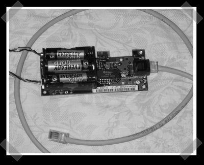
[Jachin] sent in his network port tester built from a network card, wake on lan cable and a battery holder. Three AAs supply 4.5v DC just like the motherboard would to the card via the WOL cable. Nice trick, I’d consider adding a static bag at the least to keep the card from getting zapped.


38 thoughts on “Wake On Lan Network Tester”
Leave a Reply
Please be kind and respectful to help make the comments section excellent. (Comment Policy)


good stuff, interesting. great idea
Okay, I don’t get it. The instructions differ from the picture quite a bit.
Looks like he is giving the card the 4.5v it expects from the motherboard, then you plug a WOL cable into that modded card and a regular one? Why not just hook the 4.5v directly to the WOL card? What exactly is this even going to tell you? I don’t get it…
dosn’t look too “finished”, but seems handy
when I said “why not just hook up the 4.5v to the WOL card” I meant “why not just hook up the 4.5v to the WOL cable”..
Still don’t get this…
n3ldan – It’s a network connectivity tester. You plug a patch cable into this gadget, and the other end into a jack, and if there is connectivity, the project card will light up. He mentions this in the “why” section of the project.
Anyway, this is a great idea, and I’ll definitely be making one for work. I can’t count the times I’ve had to test jacks that haven’t been used in years, and needed to lug a laptop around to do it.
re: what it will tell you…
If you plug this into a network port, you can immediately tell if the port is ‘live’, e.g. is connected all the way back to another network device, such as a switch. Not so much of a interest to home users, but useful in a building with 1000+ network drops. We bough a $500+ LanFluke and this ability (testing network connectivity) was the most used on the device.
Also, he is only plugging the 4.5V into the WOL power plug that is on the card because that is where the card expects power to come from when the PCI bus is not providing power. He is just simulating what state the card is in when the the computer is turned off.
“4. when I said “why not just hook up the 4.5v to the WOL card” I meant “why not just hook up the 4.5v to the WOL cable”..”
…thats what he is doing.
Oh, I get it now. For some reason I thought he was plugging it into another computer’s nic…
although i would have liked it if the author of the article said what kind of card ended up working for him, since he said that 3com and d-link didn’t work.
It seems like there would be a much more elegant way to detect if the cable is properly connected…
Plus, all this is going to tell you is if the cable is connected to a switch somewhere upstream. It can’t tell you if there is actually any TCP/IP connectivity. You would need a laptop or PDA with Ethernet (like the Zaurus) to test that, so you might as well just use the laptop/PDA in the first place.
Isn’t this exactly what cable testers like this one do?
http://www.geeks.com/details.asp?invtid=SS35407-TEST&cpc=SCH
My first guess was that it was an intel 10/100 pro ….
I looked up the OID of the MAC and it is an intel.
I looked up the FCC ID (go here for more info https://gullfoss2.fcc.gov/prod/oet/cf/eas/reports/ViewExhibitReport.cfm?mode=Exhibits&RequestTimeout=500&calledFromFrame=N&application_id=92736&fcc_id='EJMNPDALBANY‘)
and it is an intel 100+ pro.
I guess I pretty close …. lol, its kinda sad I could tell what family it was from with just that pic.
@ Triikan
No. that thingy only checks if the cable is assembled correctly.
What this does:
Say you are in an office where there are 40 PCs and 100 RJ-45 wall jacks, and a router with 50 ports on it. You need to find one of the 10 wall jacks out of 60 that are both unused AND connected to the office network already.
Now you could lug around a laptop, but this is a much lighter solution. When you plug the other end of the cable into the walljack and the little LED lights up, you know that the other end is connected to the network already.
Good hack.
Network FCC# EJMNPDALBANY
Intel 100 Pro Plus Network Interface Card
[url]http://www.etech4sale.com/Intel_100_Pro_Plus_Network_Interface/EJMNPDALBANY/partinfo-id-1951.html%5B/url]
nice hack, but a bit overkill for a link tester. i bet you could whip up something similar with some transistors and an led. that is, unless there is a more sophisticated protocol for establishing an ethernet link (i doubt it)
it sure seams like overkill. let’s figure out an easier way (or find a link). the upstream device is sending power on the send pair, so the downstream port should have a voltage on the receive pair. shouldn’t a resister and led work?
this is a still a great hack !!!
putting it in an anti-static bag or on conductive foam would be a bad idea. anti-static bags are conductors on the inside, and insulators on the outside iirc, so that static doesnt accumulate or if it does, the whole card is coupled to it, so it can’t do any damage. (Like how utility line workers are brought up to the voltage of the line they are working on when it doesnt make sense to turn the line off) as long as theres no difference of voltage between pins on any given chip theres no problems.
A better thing would be a project case. Wood, Plastic, or metal with standoffs.
Wow! I didn’t think of doing that!
Admittedly this particular project is possibly a little overkill. (as #14 and #15 said) drawing out the power on the patch cables and driving a LED(did I say LED?) would be far simpler.
What facinates me more, is that WOL signal wire!! :-)
I can record the MAC address of the NIC and use it for starting or stopping things. Even through my VPN to home, from work!!!
An inspiring project: Why not use the functionality of the card to turn on some device? I assume that sending the magic WOL signal to the cards MAC address would make it pusle the motherboard to wake up the computer.
I somewhat doubt that a simple resistor and led would work. I’m trying to find the standards myself, but the line voltages are either 3.3 or 5 volts. While standard voltages, the pulse duration is very small, even compared to RS232. So, the net effect is that if you see anything on the led at all it will be very dim. Very fast pulses followed by relatively long spaces will not yield any visible light. To make matters worse, its likely even too fast for a cheap logic probe.
Finnally, I am not sure if the physical layer requires an announcement before the hub/switch up stream passes anything back or not. So, you may not get any data until something intelligent says “hello, Im here!” in such case, the card does in fact do that.
And a p.s. – a cheap nic is like.. $10. which, when you think about it, you could spend close to that on discrete parts if you go to radio shack, and opt for a socket rather than a hard wired cable.
eep.. it looks like the voltage swings are 3 volts for old school low speed ethernet, and down to the milivolot p-p for Gigabit.
and before anyone says “Yeah, but the card link lights do it…” those are simulated by the ethernet processor and at best are synched to the frame, not individual bits. Precisely why the card is not such a bad choice for such a project.
yeah ok.
http://www.thinkgeek.com/gadgets/tools/6c20/
Regarding the link in #11 to geeks.com and the continuity tester:
We use one of these at work. The continuity tester is nicer in the fact that it tests for shorts and cuts along all 4 pairs, but it can’t do that unless there is a “transmitter” at the other end. The device is simple, just some resistors and LEDs at the receiving end, and a battery with some logic to charge the pairs in order. (and ours has LEDs at that end too). We spent $99 on ours, but it looks very similar to the one on the geeks page. If you plug in the transmitter at the drop, it will light if there is some network device at the other end.
The best part is you can get an inductive wand, plug your transmitter in at the drop, and go back to your wiring closet/server room with the wand, and wave it over the cable bundles. It will sound a tone the closer you get to the cable, or you can stick it in an empty RJ45 jack and it will sound really loud. Makes it easy to map your wiring or find a specific jack if you are unlucky enough to be in a place that wasn’t properly mapped to begin with. The wand will set you back about $180 (probably less, we paid more out of convenience in a large order). Both the continuity tester and the inductive probe were made by Tempo. The wand is a 200GX Inductive Amplifier with a LAN Toner 2 AT8L, the continuity tester is a 468R and 468T.
Cool hack though. It will just tell you the active drops, it doesn’t tell you WHICH drop it is. Just that it is live. And it doesn’t tell you if the wires are all correctly set. This only tests the send and receive pair, not the extra 2 (used for Power over Ethernet and I believe gigabit ethernet, maybe CDDI too)
any more thoughts on how to use this for remote control of other things than pc’s?
my dad’s a tech freak and our house has rj-45 wall plugs, so it would be really nice if i could WOL my TV or some other device. :D
HI
so id played a little bit around whith the wol function and hey guess what EVERYTHING! could be turned on whith this funktin.
After the magic packet is sended the signalline(pin3)is up to 3,3V.
To reset these 3,3V the card has to be disconnected from power.
So if the card is disconnected everytime the WOL packed is sended it would be makeable to make some kind of a “serial” protocol so more devices could be controlled over just one card/mac all over the world ;)
If there is a interest on that i try to make a litte project out of that
So if anyone is interested just mail me
Atlantis
by itself, this hack is a bit of an inelegant solution. however, by utilising the WoL pin it suddenly becomes uber-useful. I will definitely be using this and writing it up.
the comment about the anti static back was quite correct, so hows about an inside out antistatic bag? insulates the NIC’s bits from itself, throws a conductive/protective sheath over the whole lot.
shouldnt be too hard to turn on just one device via a normal and a bistable relais and a normal one. just wire it up so the WOL 3.3v triggers the normal relais which then gives the bistable one a jolt and resets the NIC to 0v. the bipolar relais would be switched everytime a magic packet is arriving.
no need for a serial protocol. theres no way of sending back things to the pc in an easy fashion anyway.
>> via a normal and a bistable relais and a normal one.
i meant just a bistable and a normal one. sorry
Wonderful idea, beats the hell out of Fluke testers, mainly because of cost. Spent about a dollar at radio shack to make one, works awesome, defeats bringing laptop and is small enough to fit most anywhere, even those tight behind the desk spaces!!!!
~ChRoNo16
BEHOLD! a cable tester is 10 bucks on ebay, and works thru a LAN as well.
I would like to ask a question about the possibility of creating just an active port tester. This project got really close to the mark in regards to downsizing the original hack but then got diverted into the WOL project. I need to come up with a small LED (light/no light) port tester. I don’t have the luxury of putting a tone or pulse on the opposite end, besides if I could do that I would just look at the switch lights. I know the RX pair has insignificant power to light an LED but I was thinking a battery hooked to an LED with a in-line circuit that could be closed by the small voltage present on the RX pair. I am not very knowledgeable about any of this but I am trying to learn. The original project would work but for my requirement I do not want or need the presence of a MAC. Although I guess I could use a read-only patch cable between the tester and the wall port… I would still like to cut the unnecessary components in order to make a smaller and sleaker tester.
We bought these linkchecks from smartronix for $20, tells you if the drop is active and the speed. They are tiny and work well. http://www.amazon.com/Smartronix-Linkcheck-Ethernet-Tester/dp/B000RGI6R6
What I really want is something that will pull an IP to see what VLan the drop is connected to without a laptop.
What is the link to the guide building the ethernet card tester, the link is not working.
OR
Could someone please tell me which wire of the WOL to connect where?
Cable tester traces the continuity of cable to ensure high speed in a network.
Does anyone have the link, or the instructions for this project? Because, it seems that the links given are not working anymore and I cannot find it anywhere else. Any help, would be appreciated.