As far as battery technology goes, Lithium Polymer cells are the bee’s knees. They’re powerful enough to handle very demanding applications and come in a multitude of sizes for any conceivable application. There’s a problem with LiPos, though – they have the tendency to explode when charged incorrectly. Luckily, [Paul] sent in a great tutorial on building a LiPo charger that works over USB.
In the original design of [Paul]’s board, he chose a Maxim MAX1551 Lithium battery charger. Confounded by the expense and/or unavailability of this IC (although Sparkfun has a few), he moved onto the similar Microchip MCP7813. This IC supports charging from a power source from 3.5 to 6 Volts as would be found in a USB hub.
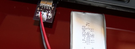
The board [Paul] came up with is incredibly small – just barely larger than the USB plug itself. The layout is fairly simple as well. We’re thinking this could be a highly useful application of some home board fabrication. If you have a simpler way to charge LiPos that don’t require a specialized chip, send it into the tip line.


Ah yes ebay is always a good reputable source for buying components that are designed to prevent something from exploding!
Well sometimes you really don’t have a choice. Mouser and other stores charge more than 20€ for delivery, even if it is just a chip. Ebay is the cheapest by a lot and you just have to trust the reviews.
you always have a choice to pay more for safety vs taking the risk of getting something mislabeled, counterfeit or poorly made or just a slug and risk getting hurt or burning your house down.
even now that you bought them you have no idea if these are real or counterfeit.
also there are lipo charging ICs all over the net with cheap shipping you just have to look.
Wow. At those shipping rates I’d probably just buy the cheap ebay charge controler chip too. Just stick it in a heavy metal box and run it through a few dis/recharge cycles. If it catches fire don’t buy from that ebay user again.
Tell that to the US Military. If it’s good enough for missiles, it’s good enough for me. ;p
haha except it was not and they had a huge problem with it XD … apparently using a 22mhz crystal in a 16mhz guidance system causes timing issues XXD
Military ? Missiles ? Timing issues ? Sounds like a funny Story. Tell me more
Contractor switched out the chips to make a few extra bucks. Was causing issues with the guided missiles (go fig).
http://www.military.com/news/article/fake-computer-chips-threaten-military.html
But sometimes you can get a real bargin on eBay like this USB hard drive enclosure. Only £910.20.
WTF? Worse is they’ve sold over 500 already.
dont get me wrong i LOVE ebay i just dont think you should be buying things there that could … explode XD
That might be a way of laundering money.
I have been seeing that a lot, some sellers put up an item and sell it at a decent price for a month or so, and suddenly the price is over $100. Has happend to about 10 items i had in my watch list.
My thought is that either they try to trick people into adding them to their watch list and later buying them without looking at the price, or ebay has some sort of charge for removing an auction before it has ended and they have run out of the item so they set the price at a level where noone would buy it.
The answer is yes- there is a rather substantial dunning for early cancels, often exceeding one’s potential profit on low margin items.
I have been using Li* batteries in all my portable projects for the last 5 years. I usually use old laptop cells, when a laptop is done with a battery pack the cells are usually good for many years and many charge cycles at lower power.
i bought some cheap protection circuits off DX (and tested them of course), they work fine for both undervoltage, overvoltage and overcurrent. Overheating is not a factor in my applications since i rarely draw more than a couple of amps, and never charge at high rates.
Well, if you click on the ‘552 sold’ link, you’ll see that it was sold for 10.20 GBP. Maybe they raised the price as an experiment, maybe to try and scam, maybe to stop selling them without removing the listing, who knows?
Could’ve just been due to the lunar new year celebrations. Instead of pulling the auction completely (and having to recreate it) they just bump the price to something silly so that people wont buy it.
I have had this happen now and then since november, so it’s not just lunar new year.
if you click on the “552 sold” link you’ll see that they bought it at £10.20… I think £910.20 is a misprice as it’s most likely £9.1 or £9.2
I also thought it was a typo (on another item), so i wrote to the seller (a chinese/taiwan company) about it and they told me it was because they ran out of stoc.
I also thought it was a typo (on another item), so i wrote to the seller (a chinese/taiwan company) about it and they told me it was because they ran out of stock.
tahaha. touche.
Improvements over this?
http://www.sparkfun.com/products/10161
Cheaper, smaller, made it myself so I can include it in future circuits. More flexible options with Microchip’s selection of chips : http://www.microchip.com/ParamChartSearch/chart.aspx?branchID=9011&mid=11&pageId=79
They have chips that can charge more than one cell at a time. Not doable with that Sparkfun charger.
Its sexy! I have made a ton smaller than this tho. But i used a Mini B USB Connector. What i would recommend to save MONEY and PARTS is to create the actual USB TYPE A Part on BOARD… like with traces… That looks like a Gold plated PCB as is so it would have been ok.
For the heck of it, I went ahead and tried to do as you said–lay out a PCB that includes the USB plug (not as a separate component, but as part of the PCB, like the USB business card), and not only was I able to get a smaller overall footprint, I was able to do it on a single layer, with no vias. Overall dimensions: 0.875″ x 0.55″, including the USB plug (0.475″). Replace the plug OP used with a 2-pin right-angle pin header, and it goes down to about 0.75″ length.
I got called out for not providing links, so here it is:
http://blog.allgaiershops.com/2012/02/01/shoot-the-engineer-and-start-production/
I used the XC6802A42XMR in a project, which is cheap in quantity (0.70), but I can’t find a source for one or two today. Maybe somebody else can.
It is similarly simple – 1 IC, 1 resistor.
Mine was a sample picked up at a show. Should have grabbed a handful :)
You can buy them at Mouser for $6.95 shipping + $0.60 each for up to 1 lb of them. Is that cheap enough?
They’re $0.34, min qty 5 parts direct from microchip, shipping $6.78 for the first 3kg. They’ll take a CC too.
http://www.microchipdirect.com/productdetails.aspx?mid=10&catalog=buymicrochip&category=MCP73831
@slurm
the us military got a bunch of cheap chinese parts that were removed from trash PCBs than sanded down and rebranded XD
a bunch managed to not be inspected and landed in us military equipment.
And since I highly doubt the US military would buy their stuff on Ebay, it means that you can get screwed, Ebay or not.
Fact is that on Ebay there are scammers but there are also many legit sellers. Counterfeiters usually clone batteries, memories and expensive chips, not stuff for low cost electronics. If you buy a pack of opamps you’re safe, but stay alert when bidding on phone batteries or memory cards.
i never said ebay but they were non-reputable Chinese suppliers without regulation or very resilient to lash back caused by faulty parts exactly the same as any overseas supplier on ebay.
Parts brokers. The guys that come up first in the Google searches when you type in a part number you can’t find at distributors. They always say they have thousands but you have to ask for a quote. If you need the part badly enough to pay the ridiculously high price, they’ll sell you something that may or may not be a working copy of the part you’re looking for.
Never buy stuff from those guys…you have no idea what you’re getting. A company I used to work for got screwed bigtime by one of them. Junk parts at premium prices.
I would think you could get away with leaving the USB connector component off and designing traces into the board that woudl mimick the connection points of the usb port. With the right thickness of board this can make a pretty solid connection.
You can build a Lipo charger with a low end microcontroller if you want to. You do need an ADC to check the voltage, but something like an ATTiny13 would be fine.
The Lipo charging curve has three stages: preconditioning, constant current, and constant voltage. All are based on a current value called ‘C’, the mA/hr rating of the battery in question, and a voltage called ‘Vreg’, the battery’s nominal voltage.
Preconditioning supplies current at .1C while the voltage across the terminals is less than 2/3 Vreg. For most Lipos, that’s about 2.8v.
Once the voltage across the terminals reaches 2/3 Vreg, the circuit moves to constant current mode. It supplies current until the voltage across the terminals reaches Vreg. The amount of current varies with the design, ranging from .2C to 1C. Higher currents charge faster, lower currents charge better. You never want to go higher than 1C though.
Once the voltage hits Vreg, the circuit moves to constant voltage mode. It reduces the current to keep the terminal voltage at Vreg until the current falls to between .03C and .07C.
http://www.hardingenergy.com/pdfs/6%20Lithium%20Polymer.pdf
Many batteries have a temperature sensor that warns you when the battery is getting too hot. You can also add circuits for reverse bias protection, overcurrent protection, discharge cutoff if your charger is built into the circuit that uses the battery, etc.
The reasons to use a dedicated chip are the usual ones: cost, size, and simplicity. The MCP3811 costs about 50c if you buy a single one, 39c in lots of 100. The ATTiny13 costs 75c per unit, @66c per 100. The MCP3811 comes in an SOT323 package (about as big as a grain of rice) and the ATTiny13 comes in SOT8 (about a quarter inch square). You can just drop the MCP3811 into a circuit and let ir run, where an ATTiny13 needs programming and additional components to control the current/voltage.
OTOH, hardware hackers aren’t limited by the same rules that drive commercial designs, and are more likely to have a uC like the ATTiny13 in stock than a specialized chip like the MCP8311.
That’s very good info ! I thought lipos were supposed to be stored in a cool env. Didn’t know they love room temperatures :) You should have gotten the place in the spotlight.
If you’re like me and have several projects in various stages of design, construction, and testing, it’s not a big deal to throw a specialized IC in your regular order from mouser or digikey.
The chip OP used actually implements most of the features you mention–precharge, constant-current, constant-voltage, and this one even has an LED indicator for charge status. Sure it won’t do under-voltage protection or over-current protection (when the battery is in use), but a simple charger, it’s great. With the PCB, you’re looking at <$2 apiece if you get a batch of boards from iTead Studio or seeed Studio.
Thing is for many(most?)hobbyists regular orders are long time in between to toss in out of the ordinary items, in a somewhat timely manner. This small town no longer has a TV tech to ask if they would get you an time whenever they place their orders.
You can charge over 1C if you have high quality batteries.
I bought an E-Flite (reputable US brand) helicopter and they recommend charging the battery at no more than 3C. Its a 25C 150mAh cell.
It just depends whats more important to you, cell longevity or charge time. A lot of people that have remote control cars/planes/helis charge at 3C or more, so its only 20 minutes or less per charge. When you’re charging from your car’s battery out on an airfield, its better to charge in 20 minutes and wear out your cells sooner than to have to wait an hour doing nothing.
-Taylor
And I just noticed my other battery (Hyperion brand) says to charge at “No more than 6C”.
-Taylor
A simple way of charging a lipo cell is basic constant-voltage. As long as you guarantee your charging supply is at or just below 4.2 volts then it’s safe – charging is self-limiting as the cell gets to that voltage and current goes to zero.
The specialised chargers also do this in the final part of their charge profile.
If you freeform soldered this (and was as good as the electronic troll physics guy) you could probably fit the whole thing into the package of a usb bluetooth dongle.
Ohh that’s interesting actually. Troll physics really impressed me.
NEat hack and all, but the reason makes no sense. A search on Octopart.com shows at least a thousand of them available from 6 merchants. And no price more than $2.50. Compared to the price of your project catching fire, that’s cheap.
“I thought it would be neat to…” is a perfectly acceptable excuse for a hack. One of the best in fact.
thats how all mine start then when done im like why the hell did i just build this.
am I the only one who expected a custom method or an avr-controlled circuit or something? Where is the educational value in just buying a circuit that does everything for you ?
I see you didn’t visit HAD for a long time, long long time
So you can learn more interesting things.
I think his work is great, especially considering that according to his blog he is 15, so it is great to see someone that young take the time to lay out circuits and solve problems like this. And it looks like he’s just getting started. Here’s to more great, bigger, and better things from Paul.
thanks and yeah, I am 15
A device also worth considering is the MCP73831 which supports automatic re charge. could be useful in applications where the battery needs to be used as it is charging. here is one I assembled to use on a breadboard: http://sunbizhosting.co.uk/~spiral/blog/wp-content/uploads/2012/01/Lipo-Charger-f-b.jpg
Hey, guess why these current-production chips appear on eBay in ones and twos: enterprising individuals request free samples from the manufacturer, and turn them around for a quick profit.
Cut out the middle man! Request parts from Maxim or Microchip directly. They both have liberal sample policies. Whether they’ll send to the author’s country for cheap or free is another matter. If not, eBay might be adding legitimate value.
Linear Technology as well. Power chips (including Lithium cell chargers) are one of their core product lines. They also offer a free PSpice simulator called LTSpice IV
I noticed that these cells tend to degrade very quickly in storage, the capacity loss on the typical cheap ones used on model helicopters and digital picture frames can approach 70% in less than six months.
Can anyone suggest a fix?
They degrade over time, regardless of use. Keeping them cold, or near 50% charge, slows down the degradation process. Doing both will *greatly* increase the longevity. But to do so, every time you want to use a battery, you’d have to:
1) Take it out of refrigerator.
2) Charge it to 100%.
3) Use the battery.
4) Charge/discharge it to 50%.
5) Put it back into refrigerator.
Is it worth it? That depends. :)
I used the MCP73831 to make an adjustable parallel lipo charger for those little lipo cells you find in mini RC helicopters :)
http://i.imgur.com/3pUBZ.jpg
DIP switches select 100,200,300, or 400mA charge rate. I’d usually slow charge these cells at 100mA each, so I set the switches depending on how many i’m charging in parallel. Each switch just adds a bit more parallel resistance to the chargerate pin. Tristate pin for status LEDs give you Red, Green, or both LEDs on. Mini USB for power input or via a header.
50c or so for the chip, an input and output capacitor, and a resistor for charge rate setting, and you’ve got a complete lipo charging setup to add to any design. Nice and easy.
I have some worries about that design, mainly about differing battery voltages possibly getting plugged directly together.
They’re only 1.25mm connectors for the tiny 130mAh lipos, and as with all parallel charging methods for RC stuff, you only plug in batteries with a similar state of charge. There’s a single 0.1″ header for charging larger single batteries.
http://www.hobbyking.com/hobbyking/store/__11857__Turnigy_nano_tech_130mah_1S_25_40C_Lipo_Pack_Kyosho_Eflite_Parkzone_Etc_.html
These are the mini lipos i’m talking about.
The only thing i can see with the design is thermal dissipation. The datasheet state that you should have as large copper area as you can to dissipate heat from the IC.
My design:
The resistors are to small for the pads, but i used what I had laying around :)
I use a clear shrink-tube as protection.
http://tinyurl.com/7zptz29
http://tinyurl.com/7636pef
http://tinyurl.com/7wj7dxu
http://tinyurl.com/7bf8n39
/// lond
Nice one, I saw that on the datasheet but my IC doesn’t seam to get hot.
Doesn’t it protect itself against excessive die temperature by shutting down until cool? It could be overheating and you’re not noticing it perhaps.
I think not, it doesn’t have a built-in temp sensor
I’ve been trying to build a charger to reliable explode a battery. The batteries have too many safeties and the best I could get was a gas vent…
If you want reliable flame, you really should go with RC aircraft LiPo, they generally have no protection and can handle enough current to get really hot. Then just charge them at really high current.
I’ve always figured you could rig up a device that would jab an ice-pick through a charged cell. Thats supposed to be enough to do it.
Plenty available:
http://www.findchips.com/avail?part=MAX1551
yep and it’s over $1.
MCP73831 is under $0.50
Well that takes care of the charging circuit. Anyone know of a good source for reliable, cheap Li-Po batteries?
Something along the lines of what the author is using.
Not the cheapest, but they carry a reasonable selection now and should be decent quality http://www.sparkfun.com/search/results?term=polymer+battery&what=products
I usually order from these guys if I want lithium polymer batteries. Most of the batteries even have the option of adding on a protection circuit.
Hehe… I use to charge LiPo’s with my bench power supply. Short bench PSU and set current limiter to whatever maximum charging current you think is suitable. Then un-short it and set output voltage to about 4.1V. Then connect the cell and a DVM. When voltage over the cell reaches 4.1V disconnect the battery and then you’re done! This requires constant monitoring though. Don’t leave the house/room while doing this…
If you have a decent PSU it is probably at least as reliable as a cheap charging circuit, and if you set the voltage to 4.2V and the current to 1C it is the ideal charger.
You should obviously not do this if your PSU has jittery regulation…
As for cheap LiPo, if you just need small (130mAh) ones you can get them at about a dollar each plus a few dollars shipping per parcel from Hobbyking. Those will be high current cells too.
HobbyKing used to have those 130mAh Turnigy (not nano-tech) ones for 50c! Wish I’d bought more of them now.
Cheap batteries: prepaid phone of choice from wally-jart. ;)
I use a $4.50 HobbyKing battery charger.
This is not an advert for HK, just a repeat customer. For a 1-off, or few-off project, why even bother making your own PCB and sourcing parts, and finding an enclosure, and assembling it all, when you can get it all done for probably better than the same end price anyway?
http://www.hobbyking.com/hobbyking/store/__7637__Turnigy_balancer_Charger_2S_3S.html
Some people want to learn how to build a charge circuit so they can put them cleanly into figure projects.
So the standalone charger may not be useful, but its way cleaner next time around when you want to add the charge circuit to your project rather than stuff some 3rd party charger in there.
I got the TI bq2000T as a free sample. Actually, I have a ton of chips from TI that were all free.
bq2000T is a Switch-mode Multi-Chemistry Battery Charger with current and temperature sensing.
http://www.ti.com/product/bq2000t
To the designer: the link on the page to the dorkbotPDX order adds the ) to the clicked link making it fail.
yeah and the Microchip chip is wrongly lablled.
Hi, good day.
I’ve my own design, but is MAX1811 based. Small board, for JST and Molex connectors. Also runs at 500mA USB. See it at:
http://rusticengineering.com/2009/06/11/usb-single-cell-lipoly-charger/
and
http://rusticengineering.com/2010/03/10/lithium-polymer-battery-usb-charger/
Thank’s
really sweet
Thats actually a nice charger. Thanks for posting it.
Nice build!
Yep you can get the MAX1555EZK+ as a free sample @ Maxim.
I get scared off of SMT boards that require reflow soldering. This board’s small, but SOT-23 so the pins aren’t THAT close together.
I’ll have to try out the Dorkbot PCB service – been meaning to do that anyhow – as I don’t trust my relatively recently-acquired home etching skills for something this small.
Well I have a project I’d like to try to actually market involving a transmitter /controller, which seems to work really well for days with just a single 200maH lipo, as it only draws a couple of mA. It also has a USB connector for its mcu, from which 4.5 volts is available from a pin (there’s a diode in there, hence the missing .5V). Well if I’m incorporating a LiPO, I have to consider how it will be recharged, but I’m really trying to keep costs down so I tried an experiment. Took the 4.5V source, added another diode (down to 4V now) in series with a 10 ohm resistor, and tried charging the battery from this arrangement when the USB is plugged in. This amounts to about 80-100mA of charge current for maybe 1/2 minute when the battery is down to 3V, and that quickly drops to a few tens of mA after a few minutes. OK, its a really slow way to charge the thing, but after about 3-4hours the battery is up to nearly 4V, the current is down to a couple of mA, and its ready to power the circuit for a couple more days.
I realize that with just a few more parts I could use that MCP73831 circuit mentioned in the article, but the data sheet seems to suggest a couple of 4.7uF capacitors, and my simple diode/resistor combination sure seems a lot cheaper. I seriously doubt charging like this would ever pose a safety risk, but whats the down side?
I’ve heard all these discussions on and on about the “optimal” way to charge lipos, but I haven’t seen much data on how much it hurts to charge them in a slightly less optimal way. If it means the battery charge cycles or performance will eventually suffer, the question is by how much?
Sounds like your method will only lengthen the life of the battery.
Well as it turned out, the devil being in the details, it didn’t work out quite as I’d planned. Turns out that as the current gets lower and lower, the forward voltage drop across the diodes can get significantly less than the expected minimum of about .5V. So if left charging long enough, the LiPO voltage will eventually begin to exceed the 4.2 v max limit. So I’ve bitten the bullet. I decided on a MAX1555 chip. Very tiny, pretty cheap, and its charge current is ideal for my mAh battery rating.