[Doctor Bass] needed to do some welding on his electric bicycle. The problem is that he’s never welded before and doesn’t have any tools for it. As you can see, that didn’t stop him. He used a bicycle battery made from reclaimed DeWalt A123 cells to power his diy welding rig.
He has a huge adjustable resistor which is responsible for limiting the current. 80 Amps seems to work the best with the welding rods he’s chosen. It is worth noting that when he shows off each part of the welder (see the clip after the break) the color of the wire used for positive and negative leads is opposite of convention. His positive wiring is black while his ground connection is red.
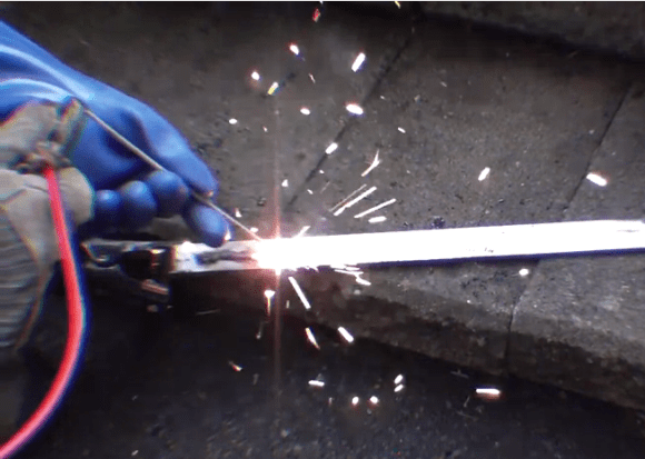
To get the welding under way he connects a jumper-cable-like clamp to his work piece which serves as the positive electrode. To hold the welding rod he drilled a hole in a pair of vice grip pliers and bolted on the negative lead. This way the end of the welding rod can be clamped in the vice grips while his other hand guides the tip. So far he’s still practicing, but it looks like he’s nearly ready to take on the job at hand.
http://www.youtube.com/watch?v=WsD-xU4gtHM
[Thanks Ryoku]


now combine this with the 9v-battery hack earlier, and we have a hack worthy of McGyver (the tv charater, not the one commenting on this site:-P )
MacGyver just used a car battery when he needed to weld something. Oh and pennies I think it was. Don’t ask me which ep though :P
Season 1… somewhere around episode 5 or 6 maybe… It was the one with the Rancher and the Ants.
coins, jumper cables (I think?), and I can’t remember what he used for power, car batteries perhaps?, used the rig to repair a connecting rod I think, to get an engine running again.. been years since I’ve seen the show, but I always remembered bits and pieces of that episode.
I’m pretty sure he used a quarter to weld a new electrode on an outboard motor’s spark plug. He used a nail for the electrode. It’s also part of the opening title sequence (because of the nice sparks ;).
he used a quarter and a gas powered generator to weld a piston in a gas powered water pump in one episode… MacGyver only has like… maybe ten tricks or so. he uses the same ones over and over. the fire time delay gun firing thing, the beer keg(or canister of generic gas busting down a door(or wall), the welding thing… used over and over again.
MacGver really is… not a great example of being a maker or anything… he takes perfectly good items and uses them for something else to escape or whatever. i love him, but he destroys things… often unnecessarily.
Nice, really cool stuff. Welding looks like a lot of fun, I must say.
It’s loads of fun. You just need know if you want to weld stick,TIG, MIG, or flux core and after that, you might as well learn to use a cutting torch, because now that you ccan put it together you should know how to take it apart, so cutting and washing with a torch and welding kinda go hand in hand. After you know a little of both, go work as a tacker/helper at a shipyard where you’ll be able to run a welding machine until your hearts content, or until you get sick of it and then some… :)
I have a question:
What are the other options for current regulation in what is essentially a very high current DC power supply such as this??? I am aware of several “do-able” methods of achieving very accurate and variable voltage regulation, but the only three methods I have seen for controlling current are:
1. Using a large resistor….. Basic Ohms law at work here
2. Using a large power transistor in series with the current, with another ‘control’ transistor that diverts power away from the base of the series pass transistor
3. Using an inductor in series and then providing pulsed DC to it via switching from a power transistor such as an IGBT
————————
The problem that seems to be present in all three of these methods is that you effectively have a large resistance which wastes a lot of power in the form of heat losses.
This is true whether you use an inductor’s effective resistance or reactance, or the losses in a transistor too…… I mean basically all that is happening is that you are using a transistor as a variable resistor.
Or am I confused?? I admit that I am very much an electronics newbie, and I am studying on my own as there are no schools that teach things like this is my country….
The reason that I am so interested in this question, is that I would like to build a MPPT controller for photovoltaic solar panels. I am good to go on all parts of the project other than lacking understanding of how losses are managed in current control.
The usual method of controlling current in these types of MPPT devices seems to be to vary the frequency and pulse width of a pulsed DC current into an inductor….
Thank you for the consideration.
The first two are acting as a resistor and wasting energy. The last can be very efficient (>90%) as you’re using the power device as a switch (either all on or all off) and using the inductor as a filter to smooth out the current from there.
I think that your options 1 and 2 lose power to heat because they act like resistors, but option 3 is efficient. The reason is that the transistor is always either on or off, not halfway, and so it doesn’t act as a resistor. The reactance of the coil doesn’t cause power loss either, rather it stores power in much the same way that a capacitor does. There is of course unintended resistance in the wires and the transistor that will lead to losses, but overall the efficiency can be rather good. Disclaimer: I am not an electrician!
Of course! The energy is stored in the magnetic field and thus is “going somewhere” where is will be taken advantage of rather than simply going to waste as heat…..
Thank you for the insight which I had somehow forgotten and overlooked.
As I said, I am very much still a newbie with no schooling….. But I am learning fast!
Thanks!
Another question:
How is a proper value for the series resistance calculated in an instance like this?? Do you assume that the welding rod/ substrate interface represents essentially a “dead short” with negligible resistance, and that the current flow through the circuit is substantially controlled by the value of the large series resistor alone?
Which in this case {~80 amps, at around 40 volts} would be around 0.5 Ohm???
Or am I misunderstanding and the resistance in the “welding” part of the circuit is substantially higher thus shouldering more of the overall voltage drop in the circuit? It would seem that if the “welding part” of the circuit has an extremely low resistance that the huge voltage drop across the series resistor vs. the tiny voltage drop across the welding rod to workpiece interface would mean that very little heat was generated at the tip of the welding rod…. Which obviously cannot be the case or otherwise, it wouldn’t be getting hot enough to weld?????
I don’t think I can fully answer your question but I may be able to give you some insight, It seems you are assuming a low resistance at the “rod to workpiece interface” because it is metal to metal contact, but in actuality there is no contact. There is an arc between the rod and piece, and this deposits the vaporized (plasmized?) material from the rod onto the piece. When he first starts welding you can see he touches the rod to the piece; this is called scratch starting and it is needed to overcome the air gap resistance and start the arc
The heat needed to weld is not generated by resistance in arc welding, rather the arc itself is intensely hot and vaporizes the welding rod while melting the base metal. There are different transfer methods for how the rod material gets to the base material but “vaporized” describes the overall idea pretty well.
80 amps through the welding rod and workpeice would likely be able to make the rod glow red but would not be enough to melt the base material. Honestly I don’t know why an arc creates so much heat vs. resistive methods (like spot welding).
The series resistance of the circuit is dominated by the current limiting resistor. The rest of the circuit can be considered a short at this current level.
We really need an edit button. To determine the size of the current limiting resistor for a case like this you use good ole Ohm’s law, dropping the entire power supply voltage across the resistor and calculating for the desired current. Choosing the current would be more a function of the power supply and thickness of the base metal/welding rod. I think the limiting factor in this case is the power supply, he has to keep the current draw within safe levels for the battery packs. When using the “MacGyver” car battery technique this is not as important, usually a makeshift resistor is made from a piece of wire smaller than the welding leads so that the small wire’s resistance dominates instead of the battery’s internal resistance or the resistance of the welding leads (car batteries can deliver up to around 1000 amps depending on model).
This is where I am getting confused. If the current flow through the circuit is almost entirely dictated by simple Ohm’s law based on the resistance of the series resistor,
then that would mean that the voltage drop across the “welding part” of the circuit was very small. That would mean that next to no power was dissipated in the weld part itself.
The arcing part of this circuit must have a substantial resistance relative to the resistor in order to be dissipating any power at it’s location, correct????
My real question again is: There must be some other way of determining an appropriate series resistor to use, as the arc itself is certainly presenting a certain resistance???
If the arc had no substantial resistance relative to the rest of the circuit, then there would be no voltage drop across it, and no substantial power consumed at that point in the circuit…….
How is this unlike the way that it works when you have a lightbulb attached to a battery by wires….. Essentially all the voltage drop is across the load which is the lightbulb, and there is next to no voltage drop across the wires themselves, which is the reason that they do not overheat…….. If you connect wires to short circuit a battery with no other load, the entire voltage drop is across the wires alone, causing an enormous current to flow due to their low resistance……
number 1 and 2 use the series resistor method indeed (with the second the transistor being a variable resistor)
the third option is potentially a lot more efficient. with the pulsed dc, you limit the power by varying the duty cycle. with a 50% duty-cycle the average voltage will be 50%. the series inductor is only there to “smooth things out” (and some other reasons, but those will be a little harder to explain) so no losses for a series resistor
most switching power supplies are at least 80% efficient.
[quote] This is true whether you use an inductor’s effective resistance or reactance[/quote]
note that the reactance is only there when the voltage across the inductor is changing.
when you use a sinusoidal signal the XL(inductive reactance) will be: (omega)*L
omega: the angular frequency in [rad/s]
L: inductance in [Henry]
Someone should make a small schematic over the three methods – the third one reminds me of switch mode power supplys.
A123 cells are pretty valuable. You could SELL those A123 cells for enough to BUY a decent welder!
The traditional method is to use several old car batteries in series. 36v is enough. The classic “MacGyver” method is a set of cheap jumper cables, connected to 2 or 3 car batteries (still in the cars!), and coathangers for welding rod.
Perhaps the cells are part of his electric bike project. Hopefully his monitoring will keep them from crapping out.
+1 for coathangers, lots of fun
A coathanger welding rod is going to give you worthless welds. You need some kind of shielding to protect it from the atmosphere. Small welding rods are very cheap and there’s no reason not to just buy some.
I notice no-ones commented that whilst welding, he is pushing the rod into the weld, as opposed to the correct pulling method. (Pushing causes the slag to form oddly leaving porous and poor welds)
Depends on the weld type, stick angle, amperage and rod type. You can do both.
the thing to really be careful of. you should really wear a welding helmet when arc welding. goggles are for oxy-acetalene and aren’t dark enough. your eyes will hurt and burn a lot the next day. arc welding produces a huge amount of UV rays which will cause a bad sunburn in only a few minutes 10 minutes welding is like 10 hours in the sun they say. i mean, you’ll live but being all sunburned and feeling like you have sand in your eyes really sucks.
I knew a guy who did this in highschool welding class, he thought he would be all cool and use the torch goggles. A week later (doing it a hour a day in class) he had a VERY nasty sun burn. Like skin pealing off his face bad. It was pretty funny.
The best helmets are the ones with auto tinting, it’s a pain in the ass raising your helmet, positioning yourself, putting your helmet on, then starting your weld only to find you moved your hand a bit and are welding in the wrong spot.
Looks like fun, but there isn’t a lot of heat in that weld. I pray that those are not cutting goggles. They may not be enough protection for his eyes.
I can say by looking at that video a few times they are maybe 5 lenses. I was somewhat horrified when I saw that he was wearing artificial fabrics and basically kitchen rubbers D= sound example of how a maker can weld with little to work with other than whats on hand. that is if you happen to have a 1k resistor handy, just saying.
I would be concerned about a few things. First, if you can see through the “googles” they probably aren’t dark enough for welding. In particular, they may not block UV. I mistakenly looked at the wrong time and was “sparked” and saw the spark for several days even though I looked at it for a split second. One reason why welders wear masks is that the UV is so strong, you will get a sunburn. Having your face exposed (or neck or arms etc) is just asking for a bad sunburn.
Awesome! That does look like a lot of fun. I need to find stuff to weld now.
Just a note on your soldering technique, do crescent shapes while “pulling” the molten metal toward the points, it will help improve your welds. Nice setup
This could be pretty neat if you need to get a welder somewhere quick, just take the welding kit there on your e-bike.
Here’s a few things to keep in mind. 1: first and foremost, get a proper welding mask/hood, because if you keep welding without face protection you will get a UV burn from the ark and you need at the very least a shade 9 (I use 10-11) lense for the hood because you can get a UV burn on your eyeballs too and trust me on this, you don’t want it. 2: if your bike frame is aluminum, than you will need aluminum rods, more heat, darker shade lense for hood and a good deal of practice welding aluminum, because its a bit harder. If you can, practice a little with 7018 or 6010 rods and get the feel of them and with a bit of luck, you should do fine. BTW get some leather gloves, they can be cheap and they don’t have to be made for welding, just leather, because the rubber gloves will melt, just make sure you don’t weld in the rain…. Like me lol ;)
Just adding to Ryoku’s note of caution. Arc welding produces UV (and hot spattering slag) so use a full-face arc welding helmet (not acetylene goggles or whatever they are). Leather gloves and jacket/apron are ideal.
You can also use a large tapped inductor for current limiting and stabilization.
You can’t really use an inductor for current limiting on a DC Arc welder???? I mean… It would have no reactance since it is DC, all you would have to limit the current is the resistance of the coil. Which is what he has now lol
Cool idea, I always wanted to try something like this, but I suck at welding even with proper welding equipment. As has been noted, the goggles and gloves are pretty inadequate for the task at hand, and I would practice getting good penetration before welding torque arm mounts. We build drag racing cars at the shop, and I know firsthand how important welds can be, not just for reliability, but also for safety. Bevel the edges of the mounts where possible to help get more penetration towards the center of the part. I leave the welding to the ‘pro’ at my shop, but I often assist him and have learned a couple of things……Still didn’t learn to actually weld anything myself. ;)