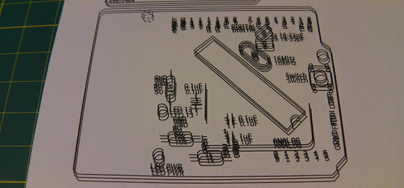
The migraine-inducing image above is the product of [Rupert Hirst]’s attempts at home PCB fabrication. He’s using the toner transfer method – printing a circuit on a piece of transparency sheet with a laser printer, setting it on a piece of copper clad board, and sending the whole assembly through a laminator. It’s a fairly straightforward process, but if you can’t run a transparency sheet through a printer multiple times your etch resist won’t hold up too well. Of course the transparency sheet must be aligned each time it goes through the printer, so [Rupert] came up with a modification that ensures laser toner goes only where it’s supposed to.
[Rupert] picked up a Samsung ML-2165W laser printer for his PCB fab shop, but printing the same image multiple times on the same transparency sheet would result in unusable masks. This problem was fixed with a few plastic shims used to hang door frames and a card stock tray that ensures the transparency sheet goes through the printer the same way every time.
We saw [Rupert]’s homebrew PCB fabrication process a few weeks ago when he sent in his six channel floppy drive MIDI synth. In his build video, [Rupert] demonstrated what is possibly the cleanest toner transfer PCB we’ve seen to date. You can check out his etching process in the video after the break.
[youtube=http://www.youtube.com/watch?v=IYQWLlBz8hE&w=580]


i don’t really mind re posts, but this one is from 2 weeks ago.
http://hackaday.com/2013/02/13/building-a-six-channel-floppy-drive-synth-from-start-to-finish/
i stand corrected, half of it was from a couple of weeks ago ;}
How about a printer that prints with conductive ink?
Then gets baked or covered with a clear coating?
I can think of 10 ways that almost work. Problem mainly being that conductive ink, isn’t all that conductive, compared to copper. Then there’s ways that would work, but use high energy and/or lots of time, with not a lot of potential for drastic improvements, such that the traditional methods of board prep seem very rapid and highly efficient.
I solved it by printing on transparants with a Hp ps 5180 (scalable printing – just put inkt output to max)
I was wondering about that. Since when I first heard of this some years back, all you had to do was print at maximum black level… so I don’t know if modern printers in general got too “idiot proof” to let you do that. Though that might have been just for DIL ICs back then, which was acceptable for that, not the spider silk thin traces we need now.
I’ve been meaning to write up a tutorial on the common mistakes in home PCB fab, and he hits the biggest one I’ve run into with photolithography. The black output on nearly all home printers (inkjet AND laser–there tend to be more sufficient inkjet printers, though, which is why people usually say to use inkjets for transparencies) is simply not good enough to expose photoresist properly. This becomes readily apparent when you buy a Stouffer step wedge and compare the darkness of the transparency outputs to the wedge–most printers simply can’t print dark enough on transparencies, no matter your settings.
The print multiple times on a single transparency trick can work very well–I found a very cheap, extra-low-end ($15) HP Inkjet (HP 1000 series?) that magically had a good enough print-to-print alignment that I could reasonably align a print on each other, and could after 2 or 3 prints get a darkness beyond the gauge. I’ve never actually tried modifying one of them to get better print consistency However, I think the alignment was as good as he could get it–the variation is on the order of 5 mils or so, meaning that if you did fine (<20 mil) traces, you're going to have significant issues. I ditched the method because of this, but found that my library's very high end lasers (highest end modern Xerox all-in-one money can buy) could print dark enough (without pinholes or variations) on transparency. The step wedge value was something like 12 or 13, good enough for most standard resists (marginal for LPI solder mask, but I've told myself to not play with that until I've gotten standard resist down)
I should make a list of printers that don't work at some point so that people don't go banging their heads for months like I did wondering why all these people online were successful and I wasn't.
*If you're having issues with the photoresist method, it is likely due to insufficient print density, not improper development times*
My main laser right now, a Canon MF43xx all-in-one (and the entire series) is most certainly incapable of the sufficient black levels. This usually manifests itself with images that have dark enough outlines but have faded interiors (that are still dark, but clearly not enough on a proper step gauge) and/or pinholing inside. I strongly suspect this is an electrostatic effect related to how laser printers operate.
You could add the OKI B4250 laser printer to your fail list
Although this is a clever hack, I have to admit I don’t really see the point. With all the boards I do, I print two copies (on to TRACING paper – in my experience, transparency film doesn’t hold as much toner) and then align and tape them together. Gives a nice dense fill, even on ground planes (and even though my printer says the toner is below 1% and should be replaced!).
I’ve found that genuine HP toner is denser than the no-name compatible stuff, so it’s probably best splashing out for the real toner.
Well the point was for etching not photoresist :)
DUH! I’m sorry, my appolloggies! I even read the article too and thought that it was neat he could transfer toner from the transparency film to the PCB, so I’ve no idea why I driveled on about exposure transparencies.
Normal service will be resumed shortly ;-)
What benefits does this process provide over photo resistive boards?
Buying plain copper ones for half the price, plus they don’t need special storage, and are easier to cut up into smaller boards, so you don’t have to plan to do 3 projects at a time to make best user of a large board.
Love the video. I wish more people post videos like him instead of wasting minutes on introducing themselves and talking useless information about their project that any one can figure out by looking at the video.
i was using this metod long ago XD is cheapest that buying a “professional” material.
well, multipass method never worked for me, at least on home Xerox Phaser as well as on Enterprise-level Konica-Minolta.
What I’ve noticed is that 2nd pass gives a blur and shadows because film is likely loosing its ability to attract toner.
Tested this with 3 different types of transparency films. Both of these printers didn’t have “Transparency” option in their drivers – that might explain the cause, even though 1st pass is always perfect.
Just like other users – I was printing 2 copies and overlaying those. The result was always perfect. 10mil tracks possible with smooth ground planes. Plus no need to hack the printer.