

Octopodes and useless plastic baubles begone. It’s time yet again for another installment of learning how to make a thing with 3D design tools. This week, we’re making something with AutoCAD. It’s an amazing piece of software that costs $4000 per seat. Hilariously expensive for any home tinkerer, but if you go to a university with an engineering program, there’s a computer lab with machines running AutoCAD somewhere on campus.
Last week we took a look at making something with OpenSCAD. AutoCAD is much, much different. Where OpenSCAD is sorta, kinda like programming, AutoCAD is just a digital version of t-squares, triangles, straight edges, and people getting uppity when you don’t call their drawing device a ‘lead holder’.
I’ve broken this tutorial down into two parts: right now you’re reading the tutorial on drawing 2D objects in AutoCAD. This weekend I’ll publish the transformation of 2D objects into a 3D printable part. Read on for how to create a 2D object in AutoCAD.
Our Thing
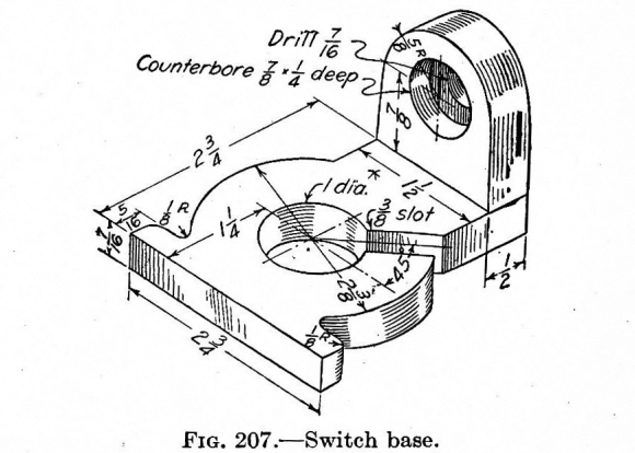
Because demonstrating different way to create a 3D printable object without using the same object each time, we’re going with this drawing again. That drawing is nearly 100 years old, but it’s still a great introduction to drawing and turning a picture into a 3D printable object.
Let’s just dig right in.
We’re going to start by drawing the top perspective of our part.
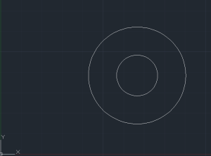
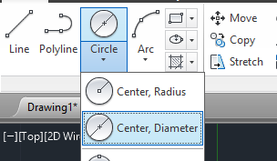 Start by drawing two circles. From the ‘Home’ tab, click on the Circle drop down menu and select ‘Center, Diameter’. This will allow you to draw a circle by picking a point for the center and entering a number for the diameter. From our nearly 100-year-old drawing of our thing, we simply need to draw a 1 inch diameter circle and a 2 3/8 inch diameter circle with the same center point.
I’ll preface this next part by saying this isn’t the right way to do AutoCAD, or any drafting app. The professional way to do this next step is to create another type of line – preferably a different color, and one that extends to infinity. This is called a construction line, and it’s the proper way to do this sort of thing. Nevertheless, I’m an idiot and this is the simple way to do things.
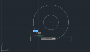
The next step is to create those little bits sticking off the end of the circles on our thing. We’ll start with the one with the weird radii on them.
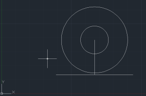
Draw a line 1 ¼ inch long starting from the center of the circles. Then, draw a line on either side of the bottom of the line 1 3/8 inch long. You’ll end up with something that looks like the pic to the right. Now, just delete that first line coming from the center of the circles, add that 5/16 inch long part on the side, and then draw another line going intersecting with the big circle.
Those corners look a little rough compared to the hundred year old drawing, so let’s round them off. From the Home tab, select ‘Fillet’. AutoCAD then prompts us to select an object and shows the words [Undo Polyline Radius Trim Multiple] in the command bar. Type in Radius, specify 0.125, and click on one line of the hard corner, then the next line. After you click the second time, that 90 degree corner will be replaced with a nice rounded edge. Do the same with the two other radii connecting the flange to the big circle and you’ll start to see the 100-year-old part take shape.
In terms of projecting this part into a 2D drawing, there’s an extra line right now we need to get rid of. It’s between the last two fillets we just drew. You can get rid of that line by clicking on the Trim button in the Home tab. It will ask you to select objects, so click on the last two fillets we just created. Once they’ve both turned into dotted lines, hit enter, click the line you’d like to get rid of, and it’ll disappear. 
Finishing off the ‘top’ part of our part, as projected onto a 2D drawing is left as an exercise to the reader.
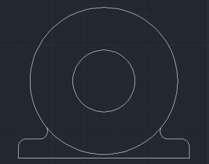
Now, there’s only one bit missing from our part, and it’s also a great way to demonstrate another tool in AutoCAD. Start by drawing a line – it doesn’t matter how long – from the center of our circles. Using the Rotate command, select this line, specify the center of the circles as a base point, hit enter, and specify a rotation angle of 45 degrees. Now all we have to do is cut a 3/8 inch slot and trim everything up. Type ‘Offset’ into AutoCAD (There’s a button on the Home tab. It looks like an upside-down letter T written in bubble letters), specify the offset distance – in this case a half of 3/8ths, or 0.1875 in decimal, hit enter, and click on the line we just rotated. Click on one side of our rotated line, then on the other side. Delete the center line, trim everything up, and there’s your part. Who would have thought you could actually convey information with an animated .gif?
There’s our top projection
Since we have a drawing of our ‘thing’ when seen from above, all we have to do now is bring everything into a third dimension. This post is already pushing 1000 words, though, and the previous OpenSCAD tutorial got a few comments appreciating how short it was.
This weekend I’ll finish off turning this drawing into a 3D printable object. It’s not especially hard, but explaining it will probably take a 1000 words yet again.


Why would you suggest to pirate it, when there are free tools available? Seriously, if you want Autocad you should pay for it. If you can’t afford it, or don’t want to spend the money, then do without or use something else.
It’s an amazing piece of software that costs $4000 per seat. Hilariously expensive for any home tinkerer, but if you go to a university with an engineering program, there’s a computer lab with machines running AutoCAD somewhere on campus.
There are a ton of free or free-ish alternatives. DraftSight is a good one. Autodesk has a pretty good academic license/trial version, too…
The point of choosing AutoCAD for this tutorial is that it’s the gold standard. All the other free CAD packages out there try to emulate AutoCAD in some respects.
I’m not doing anything with AutoCAD that you can’t do with a free package. Instead of thinking of this post as, “do X with AutoCAD”, think of it as, “do X with a CAD package”.
Right, but you highlighted the letters “p i r a t e i t” in your post. Why would you do that? Or were we not supposed to notice? If we weren’t supposed to notice, why did you do it? If we were supposed to notice does that mean you seriously want people to pirate stuff?
> Right, but you highlighted the letters “p i r a t e i t” in your post. Why would you do that?
Because I have a sense of humor.
Hahahaha.
@Brian Benchoff
That’s the problem with the written word, especially when targeted at nerds. :V
I can see how this was meant as a joke but it’s still not appropriate to suggest piracy. I’ve removed the bold tags for the characters in question.
How it’s being pirated here? If you are student you can do it for study, if you are school worker and license is per seat than it should be not problem too right? Newer mind that you won’t be modeling commercial part, but part for self use.
I agree that Auto cad is great, especially Inventor (with 3D manipulator it’s superb tool), but for 3D printing wouldn’t it be better to teach Design spark (though it really lacks if you asked me) or better Blender – which is totally different from what you imagine 3D modeling is if you ever modeled something in cad program, but it’s free and with few hours of training you can model simple things.
I have only used Blender and Maya (Maya PLE for a few years and now Blender) from age 14 to now which I’m 21.
I’ve been finding it hard to deal with CAD programs but I’m going to keep at it.
Basic 3d modeling with Blender is very nice since you have so much control, you have an underlying understanding of how “it” works. Now to get used to the higher levels of manipulating 3d and 32d geometry, or maybe there will be Blender Cad edition which would be great but probably won’t happen.
Blender is really nice to draw, but really hard if you want to have model with fine dimensions.
Blender cad would be awesome mix ^^
Schools teach with AutoCAD because that’s how students get jobs. They need to be familiar with software that they’re going to use in the real world. If a company is looking for AutoCAD operators you might not make the cut if your resume says Maya. Although I know the skill sets are similar, only being intimidatingly familiar with AutoCAD will allow you to know how to manipulate it to the level that most companies need these days. We’re not just drawing lines and circles, we’re writing LISP routines and doing tons from the command line.
Whoops, you said Blender, not maya. Sorry.
You DO realise where you are, don’t you?
In the good old days, pros would buy the software at $4000 per seat, they’d use it until a new version came out, then they’d upgrade.
To help fund their upgrade they used to sell the older software on ebay, passing on the discs and licenses code to another guy who perhaps didn’t have thousands to spunk on a cad package, (say someone who is making things for a hobby, or a inventor etc that has a day job so can’t get the student license)…
But then Autocad started getting ebay to pull auctions of the software, telling people that they couldn’t resell the software that they quite legitimately bought.
So pretty much yes, Pirate it. go steal that bad boy like it’s going out of fashion, because there is no way that you’re going to get a legitimate copy to learn on at a reasonable price without being a student.
Honestly though I prefer Creo Elements…
It really depends what you are trying to do.
For my “money” which is limited as I’m not a student.
If I wanted to model a figurine or some kind of ornament, I’d use blender. (as it’s free and very powerful)
If I wanted to model a “machine part” I’d use creo elements, (again, as it’s free and powerful).
You can get the software cheap if you have an .edu address. Autodesk has free academic versions of its software available to just about anyone with said .edu email address. They’re generally good for 3 years. Additionally, you can buy a permanent license for the academic stuff for real cheap. Yes, any prints you make will have the watermark, but it’s legit as long as you’re using it for personal learning/use.
If you don’t, then, yep, you’re out several thousand if you really want it and don’t have access to someone who does.
Or you could reproduce, send your kids to school, and get access that way. But that’s *really* expensive.
There are some decent cad packages for under $500. I’ve yet to try VIA Cad but I heard it’s decent. I’ve used Blender for a long time so CAD anything is something I don’t find fun to learn.
A bit backwards but you understand what I mean.
(wish I could edit my posts)
[EDIT] Mods can totally edit your post
I see what you did there
¯\_(ツ)_/¯
Did what?
The OP with the bold..
OFFTOP
Sorry, this article is related to 3D printing, so I just wants to ask, does somebody experimented with laser pointers in 640-1000mW (up to 1W) and thin plastic powder? I mean, does anybody know – will it be enough to melt thin layer of plastic powder? In 2014 the key patents for SLS will be ended, so looks like it should be something like what was with FDM printers after key FDM patents ending. I have CO2 40W laser engraver/cutter, but it’s a bit complicated in maintenance because of water cooling system, two air pumps (removing burning products from laser beam way and from laser cutter cover) and high voltage preservations (in addition to power plug it should have ground connection). But as I can see for example here – youtu(dot)be(slash)moWe5HNpFqI 640mW laser can cut pretty thick plastic (CD Case), so for layer in 20-50 microns of plastic powder it should be more than enough, (probably with lower speed, than for 20-40W laser). Just interesting, may be someone already have tried this.
The construction of these 3D printers is not very difficult, but they can provide much better quality, than FDM even in personal variant. If it is possible to use this kind of lasers, it will be much easier to build such printers. They can work in the same way as FDM printers working now, only few rollers will be needed and replacement of extruder with laser. (And protective cover, because this dangerous for vision).
Or, if mechanical positioning and drawing in this printer is not acceptible and laser beam should be positioned with mirrors, it is even better, because it will be possible to use few lasers and increase the speed of printing. Probably.
There are two things that are currently going on with regards lasers.
There is a laser sintering project going on over at the reprap forums.
Suffice to say it’s not easy, you need to spread your powder in a uniform and thin layer each time you need to add some height. -you need a laser capable of melting the powders etc.
Long story short, there are people doing it, but it’s not without it’s complications.
if you want to do printing with lasers look at the 1W blue lasers fgrom DLP projectors, £50 on ebay, and more than enough UV to cure UVResin plastics, (it’s also much easier to introduce a new layer.
(for example you can build your parts in a bucket, and have a bucket of equal volume next to it.)
Start with your tank bucket being lower than then part, raise it to transfer your resin to your build bucket. when you’ve finished, lower it to drain your “build” tank.
Another way people to laser cured resin is to start at the “top” of a part secure to a regular build platform, and have the laser under this. you raise the platform pulling the part that is stuck to it out of a resin layer…
(long story short, there are plenty of complications with laser cured UV plastics too)
Thanks a lot for info! I’ve found answer here – reprap(dot)org(slash)wiki(slash)DIY_Selective_Laser_Sintering_FAQ#What_are_the_pros_and_cons_of_a_diode_laser_for_a_DIY_SLS_machine.3F
“White or clear thermoplastic powder is either highly reflective or transparent for visible or near-infrared light (< 1um), which means that one have to work only with dark powders to achieve any sensible result. This is opposed to CO2 lasers operating on far infrared wavelengths where thermoplastic is opaque"
Ok, so it is possible with dark plastic like black ABS. And it will be completely recycleable. This is very good, because this kind of printing is very good for functional parts printed in one piece with high resolution. FDM printers has such possibilities like multimaterial printing and many other, but for high resolution printing the laser will be better, I think.
I probably could have gone the extra mile and found and linked that page myself!
(when you say everything is recyclable don’t forget that the more times you melt plastic the more denatured it gets, hence why most plastic after being recycled a load of times ends up being street bollards or bins, in matte black rough textured. -they just aren’t the same neat material any more.)
Also, as the page says, there is limited success in grinding plastic to make your own powder. given the hardness of a solid part as in 100% infill that some parts may be, it might be difficult to grind these parts, they’ll need breaking into consecutively smaller parts before they are going to be ready for any kind of high speed grinder.
Just having a quick read, it seems that the materials aren’t “easy” to come by.
which makes me wonder, -what might the success rate of using powder paint be? the kind of pain that you can easy buy for powder coating.
that’s layered on in a powder form, and cured into a very hard plastic with heat. -it’s available in tons of colours too -and reasonably cheap.
(I’m starting to sense a laser sintering 3d printer build in my future… -I was going to build a small laser cutter/etcher anyway, so why not just add a Z)
Yes, polymers will be denaturated in appropriate amount after each recycling. So, I think some byochemistry (with microorganisms which can produce source materials for plastics) will be needed for real recycling (from CO2 and H2O to polymers). But I think this is not critical for now, because I think It is possible to use something like filtering and sifting of the crushed powder (not sure, need to investigate this).
The idea of using powder paints is very intresting. But I never worked previously with this kind of paints and need to investigate this also. But I think this should work, the toner for laser printer is also thermoplastic polymer.
I like in idea of use of low-power lasers that the laser can be same compact as an extruder of the FDM printer. Besides it will require analog building platforms which will heat powder and to put new layers. So it will consist of two parts That is it is theoretically possible to make mechanical part (XYZ axes) and the additional tools consisting of a working platform and the printing head which can be connected to mechanical part in turn.
Something like Dremel (as a whole system), but with “CNC-frame” with wide range of tools from small milling spindels to lasers, plastic extruders, painters, heaters and so on and with additive manufacturing possibilities. I.e. small personal manufacturing robot, which can be controlled completely from computer programms. Not sure I’ll sucseed a lot, but this is very intresting hobby :)
BTW, yes, as I see now it is completely possible to build small personal laser cutter with low-power diode lasers. As a start for SLS printer. Very good idea. The only limitations is matherials, but for mechanical design and prototyping black plastics is completely acceptible.
If you are in the UK and have a .ac.uk or other university email address, Autodesk makes all their packages available to you free of charge. All the autocad suites and much much more :D
Let’s not encourage people to use “$4,000” software. Really, at that price I don’t believe it’s about Autodesk just trying to make a reasonable profit on something they put tons of R&D in, (Not that I don’t believe that they did) It’s about someone at Autodesk deciding they are only targeting a certain corporate market where such money is no object and only that market.
Sure, you may be a college student with access to Autocad in the labs and/or special educational versions and deals. But.. they only give you that so you will invest your time and effort into learning that product now and encourage your department to spend the big bucks on it later. Believe me, those college years are great, but they are short! When they are done you won’t have access to that stuff outside of work anymore. Learn something more affordable instead.
Unless of course you like living in a world where the best tools are reserved for large companies and any hobbyist market is considred insignificant and mostly ignored, existing solely on hand-me-downs. In that case invest your time now in learning Autocad, Photoshop, etc… and make sure to encourage your future employers to keep buying all their latest versions when you get there.
Can anyone suggest a good free CAD system for hobbyists?
I’ve been trying to find a CAD system that lets me design simple shapes to E-mail to a colleague. I’ve been “tasting” all the systems listed on the “top 5 review” sites and boards I can find, and none of them seem to work very well.
Crashy, missing functionality, proprietary formats with no import/export, export by “technically correct but insane” methods, &c. The most recent was metric only (?), didn’t allow engineering scales in the project, and incomprehensible documentation. (Thank goodness for a user’s tutorial!).
What do people use? Is there anything that just allows me to make a part out of block unions and intersections?
Creo elements express, it’s free. And works rather like auto cad in that you draw lines then extrude the shape.
There are limits to the complexity of parts systems (ones that you group together to form assemblies) but nothing that the average home hobby person is ever going to run into as a problem.
Should add another limitation is the formats you can export to.
It’s pretty much proprietary formats and stl files,
But you can design whole machines and then chose specific parts to export as files ready to slice and print.
Warning, I havn’t really used any of these as I have access to a Solidworks license.
Try
http://www.openscad.org/
http://www.sketchup.com/products/sketchup-make Tips http://www.mastersketchup.com/8-tips-for-3d-printing-with-sketchup/
http://sourceforge.net/apps/mediawiki/free-cad/index.php?title=Main_Page
http://brlcad.org/
http://www.blender.org/ and http://blendercad.sourceforge.net/
Or http://www.cad4arch.com/blenderCADedition/ with http://www.cad4arch.com/cadtools/index.htm
http://www.autodesk.com/education/student-software free for 36 months for students
https://store.solidworks.com/veteran/default.php student edition $20 for veterans
http://narocad.com/
I’ve heard VIA Cad is decent from the guys on CNCzone. It’s like $150 or so.
Alibre was $100 the last time I looked, also moi is bloody brilliant and is under $200 too.
S.
Notes about this week.
Some things not mentioned that should be are the following commands;
Mvsetup: This command in AutoCad sets up the workspace, allowing the user to define the scale they are working in the bounding box to define a reference size, as well as a unit of measurement, In this case one would be using the Architecture option presented to use Inches.
UCS: will be a helpful command when wanting to draw in another perspective.
AutoCAD draws on a fixed plain by drawing a 3D box in AutoCAD’s 3D modeling mode one can use this command to switch perspectives by selecting corner nodes on the desired plain.
Other helpful commands are:
Pline: Similar to drawing a line but when closed the Poly Line is a solid object.
When using this command one can use the letter C to close the object being drawn.
Example drawing 3 sides of a box, by entering C one can have the 4th side autodrawn and close the box.
Pedit: Tool for creating poly lines out of non polyline 2D objects, as well as for editing polylines.
Explode: Explodes any object into base objects. This tool is not advised for 3D mesh, for once exploded you can not recreate the mesh easily.
(J) Join: Joins objects together. This tool can be used in bulk selection.
(M) move: Move command quick key.
Group: Groups objects. Good for organization
Layers: allows a user to color code the drawings elements. And to organize them by those colors each a different layer. Also defines line weight and allows a user to turn on and off layers with out isolating.
Isolate: A command that allows a user to select an object and see only that object.
Unisolate: A command to allow a user to view all objects.
Helpful AutoCAD commands and their functions:
Pline: Draws a polyline, which is a solid object. You can use the letter ‘C’ to close the drawn object, automatically connecting the last point to the first. For example, drawing three sides of a box and entering ‘C’ will complete the fourth side, closing the box.
Pedit: Used to create polylines from non-polyline 2D objects and edit existing polylines.
Explode: Breaks down any object into its base components. Be cautious with 3D meshes as they can be challenging to recreate once exploded.
(J) Join: Combines objects together, which is useful for bulk selection.
(M) Move: Quickly moves selected objects.
Group: Organizes objects into groups for better management.
Layers: Assigns colors to drawing elements and organizes them into different layers. You can define line weights and easily toggle layers on and off.
Isolate: Select an object to view only that object while hiding others.
Unisolate: Allows you to reveal all hidden objects for viewing.
https://keyslog.com/autocad-2019-crack/
https://forcrack.com/autocad-2016-crack/