
This week, we’re starting off with OpenSCAD, a 3D modelling program that’s more like programming than drawing. A lot of useful 3D printable objects – including the parts for a lot of RepRaps – are designed in OpenSCAD, so hopefully by the end of this you’ll be able to design your own parts.
This isn’t meant to be a complete tutorial for OpenSCAD; I’m just demoing SCAD enough to build a simple part. Next week I’ll most likely be designing a part with AutoCAD, but if you have an idea of what software tools I should use as a tutorial to make a part, leave a note in the comments. Check out the 3D Printering guide to making a part with OpenSCAD below.
First, some basics
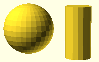
The basic idea behind OpenSCAD is constructive solid geometry this is a modeling technique that uses basic primitives such as a sphere, cube, or cylinder along with basic boolean operations to create an object. Using words to describe this technique is just terrible, so here’s a very, very short example. To the right is a pic of two objects created in OpenSCAD, a cube and a cylinder Below is the code, which you should be able to follow easily:
before
module example() {
     sphere(10);
     translate([15,15,-10]){
          cylinder(h=20, r=5);
     }
}
example();
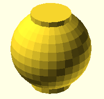
Brain dead simple, right? We’re just creating a sphere with a radius of 10 and a cylinder with a radius of 5 and a height of 20. We’re translating the cylinder in space by 15 units in the x and y axes, and down 10 units in the z axis. Here’s where constructive solid geometry comes in. We can combine those two 3D primitives by using the union() command like so:
    union(){
       sphere(10);
       translate([0,0,-10]){
          cylinder(h=20, r=5);
       }
    }
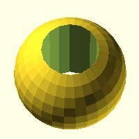
In OpenSCAD, the union command is implicit. Most of the time, you don’t need it, except in cases where you’re combining other boolean operations. There are two more boolean operations we can use – difference, or just subtracting one object from another, and intersection. Here is the difference command:
   difference(){
      sphere(10);
      translate([0,0,-10]){
         cylinder(h=20, r=5);
      }
   }
And the intersection command:
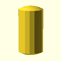
   intersection(){
      sphere(10);
      translate([0,0,-10]){
         cylinder(h=20, r=5);
      }
   }
That’s constructive solid geometry. With these boolean operations, you can make just about anything. I suppose it’s time to demonstrate that, huh?
Our Thing
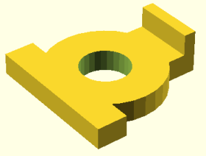
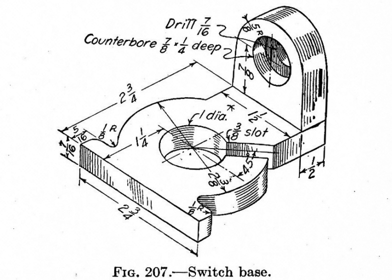 Since I’m going to be doing several tutorials of how to build a ‘thing’, it makes sense to have one standard ‘thing’ to make with these tutorials. Choosing an object to copy was unexpectedly hard, but after pulling out a few books on engineering drawing and drafting, I settled on the above ‘thing’, from Engineering Drawing (French, 1929). If you’re wondering why I chose something so odd out of a book so old, just remember: the guys who designed the Apollo spacecraft learned drafting and drawing with this book. Also, this is my column, so deal with it. By combining a few cylinders and cubes it’s fairly easy to create a very basic shape of what will become our finished part. The initial code is below, along with a render:
module thing()
{
     difference(){
        cylinder(h=7, r=19);
        cylinder(h=7, r=8);
     }

     translate([-23,10,0]){
        cube([46, 10, 7]);
     }

     translate([-10,-26,0]){
        cube([20, 16, 7]);
     }

     translate([-10,-26,7]){
        cube([20,4,7]);
     }
}
thing();
Again, this is just the beginning of our part. we’re only using cubes and cylinders here. If you’re wondering why the dimensions we’re using are so odd, it’s because the original part (published in my fourth edition copy of Engineering Drawing in 1929, but it could be from the first edition published in 1911) was designed in eighths of an inch. I’m just writing my OpenSCAD so one unit is equal to one eighth of an inch. When we print this out, we can fix any size issues just by multiplying. To finish up the main body of our part, we need to add a few cylinders on the flange. One thing that’s really cool about OpenSCAD is the ability to create small parts and later combine them with the union command. Here’s a collection of cylinders for our flange:
module flange() {
     rotate([270,0,180]){
          translate([-10,6,-4]){
              difference(){
                 union(){
                   cube([20,12,4]);
                   translate([10,0,0]){
                      cylinder(h=4, r=10);
                    }
                 }
                 translate([10,0,0]){
                    cylinder(h=4,r=3.5);
                       rotate([0,0,90]){
                          cylinder(h=3, r=7);
                       }
                 }
             }
         }
     }
}
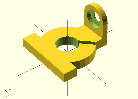
Because OpenSCAD is basically just code, we can simply call this module at the relevant space in the code. You can see this in the finalized code a few scrolls down. Right now our part looks like this: 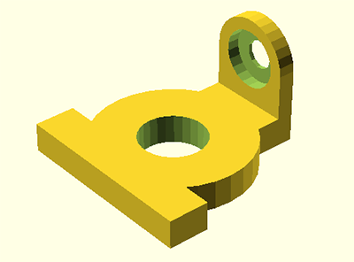 Now the only thing left to add to this thing is the 3/8″ slot on the main body, and a few fillets. I’ll leave the fillets as an exercise to the reader, but here’s the code and a pic for the resulting part:
module thing()
{
   difference(){
      cylinder(h=7, r=19);
      cylinder(h=7, r=8);
      rotate([0,0,225]){
          translate([0,1.5,0]){
             cube([20,3,7]);
          }
      }
   }
   translate([-23,10,0]){
      cube([46, 10, 7]);
   }
   translate([-10,-26,0]){
      cube([20, 10, 7]);
   }
   translate([0,-26,24]){
      flange();
   }
}

module flange() {
     rotate([270,0,180]){
          translate([-10,6,-4]){
              difference(){
                 union(){
                   cube([20,12,4]);
                   translate([10,0,0]){
                      cylinder(h=4, r=10);
                    }
                 }
                 translate([10,0,0]){
                    cylinder(h=4,r=3.5);
                       rotate([0,0,90]){
                          cylinder(h=3, r=7);
                       }
                 }
             }
         }
     }
}

thing();
So there you go. A thing, created with OpenSCAD. Is this the definitive guide to designing stuff with OpenSCAD? No, but it’s more than enough to get your feet wet. It’s enough so you can design your own parts and send them over to a 3D printer. Next week, I’ll be making the same part in AutoCAD, which should translate well to other CAD packages. If you have any desire to see this part made with another 3D design package, leave a note in the comments.


FYI, I wrote a 12-part OpenSCAD tutorial series for MakerBot that some might find helpful. :) http://www.makerbot.com/blog/2011/01/19/openscad-basics-the-setup/
I think that some of the commands used in your tutorial have changed. I went through it a few months ago and found some differences.. at least at the time. I’ll take another look, but I wonder if you had thought of updating it or if it is at all necessary?
Here’s another Openscad tutorial I found online recently. It has 4 parts so far with a 5th installment coming soon. Very well done! http://www.tridimake.com/2014/09/how-to-use-openscad-tricks-and-tips-to.html
Well done. Short and sweet so that my eyes didn’t glaze over, this is enough to lure me into trying it.
Unless I am way off, OpenSCAD units are mm. I might have included mention of the $fn option in the round objects to make them look round instead of sectioned.
As I am a member of letsmakerobots, and, there are a number of members getting in to 3d printing there, I would suggest you consider blender. TinHead http://letsmakerobots.com/user/3886 has some stuff designed in blender, and, Gareth http://letsmakerobots.com/user/2941 has also done most/all(?) of his work in blender.
In fact, OpenSCAD is unit-less, as are STL files. It is the 3D printer or CNC machine that determines the unit — in case of RepRaps, milimeters.
Excellent article/how-to!
While I prefer Trimble SketchUp (like OpenSCAD, SU’s Ruby API speaks to the coders among us) and would normally suggest you do an article on it, I’m already fairly proficient in it and think others can be as well, with very little practice.
Instead, I’d like to see you document the process of making your switch base thing in DesignSpark Mechanical.
Thanks in advance.
Forgot to mention: you guys should get some kind of syntax highlighting plugin if you’re going to post more code like that. Even one set to C(++) would make the OpenSCAD code much easier to read.
We’re working on that.Nevermind,works, but I can’t wrap images. I’ll figure something out for next time.
I added in tables (yuck!) but it worked.
Hmm… it’s a start, but not really an improvement, IMO. I actually preferred the black background (it’s what I use in Notepad++). I think the best way to improve it (other than adding an OpenSCAD keyword dictionary) would be to use separate colors for text, numbers, and punctuation (operators/parens/brackets/braces/commas). It’s probably just a matter of tweaking a stylesheet, at this point.
This is awesome. I am learning the modeling software side prior to buying a Printrbot Simple. Thanks.
Feels like programming in POVray.
Why OpenSCAD didn’t use POVray 3.6 syntax?
Indeed! why didn’t they!? povray has a great csg system with existing gui modeling software, arg.
Just curious, how does the size units work in this?
Well, everything is a unit. Doesn’t really matter what those units are until you start slicing.
but things will get dicey when you start to share those files wouldn’t it?
I’ve used OpenScad extensively for all of my modelling. It works, but there are a few issues:
The language for it is not a true programming language. It is not compiled, nor does it have a pre-processor. That means that all of your preprocessor commands are useless (like #ifdef, #define)
There are no null variables. This means you need to use workarounds on your functions to determine if a variable is set or not.
You cannot nest IF statements. At all. This is a big one. Instead your stuck using tertiary operators. This gets messy.
There are no ENUM or similar structures. You get to use arrays and simple variables. That’s all. Good luck organizing your data, because the language isn’t object oriented either.
ALL variables are global. ALL of them. That nice variable you were using was just overwritten by an include statement or a function. good luck debugging it.
Speaking of debugging, there is none. You can highlight parts of your models, set only that part to render, but you can’t view in realtime what your variables are. You can’t step through code.
Some of the functions like rotate extrude or rotate are broken. You’ll get non-solid hulls in certain situations where multiple faces are cut or joined.
The level of precision has its limitations. There are a large number of rounding errors. If you tried to put two cubes next to each other with their faces touching, but not intersecting, you will have problems. You are forced to add in your own margin which can cause other issues.
It has rendering problems if you create modules with difference in them, and use that mudule as another difference to another. the workaround is to use render() function to try to fix this, but put that render in the wrong place, and it’ll look even more messed up.
Most Useful Review +1.
I can get by with a simple interpreter that doesn’t do preprocessing and where all variables are static. I can even get by without conventional debugging tools (though lacking an output for printf style debugging would be a real handicap).
Not nesting IF statements though — I’ve seen a few little environments like this where that’s the case, and it’s a real killer. It’s just not that hard to implement a nesting stack.
Also, it’s so simle to do static local variables of the style procname_varname that there’s really no excuse for not providing for them.
Rounding errors have been a big problem for a lot of peolpe since the mid-90’s when the CS big heads got the bright idea that you should just “throw double precision at everything” without remembering that the double precision routines don’t do automatic rounding for you like the single precision ones do, and 1/10 in binary is a repeating fraction that truncates.
Sounds like a great idea that someone needs to implement right.
It does have a function to print output to the console. I use it a LOT. it’s simply echo()
For example code on what happens when you can’t nest IF statements, and you can only use tertiary IF statements, here is a simple function I created. The reason I created this function is because since it’s not object orientated, and i needed to initialize data. This returns an array with the data properly formatted.
function v_screw_hole(type, hole_allowance=-1, head_allowance=-1, $fn, horizontal=false) = [((hole_fit(screw_dia(type),$fn))+ ((hole_allowance==-1) ? ((horizontal) ? screw_hole_allowance_horizontal : screw_hole_allowance_vertical) : hole_allowance)), (hole_fit(screw_head_bottom_dia(type), $fn))+ ((head_allowance==-1) ? ((horizontal) ? screw_head_allowance_horizontal : screw_head_allowance_vertical) : head_allowance), (hole_fit(screw_head_top_dia(type), $fn))+ ((head_allowance==-1) ? ((horizontal) ? screw_head_allowance_horizontal : screw_head_allowance_vertical) : head_allowance), screw_head_height(type), 1];
Is there any reason you can’t/don’t use echo() to get the value of variables?
Some of these complaints about OpenSCAD are puzzling.
There are null variables, but the null value is called ‘undef’, not NULL as it is called in C. You can test if a variable is null using ‘if (x == undef) …’
Nested if statements work just fine. ‘If’ statements only work at the statement level, and the ?: ternary operator only works at the expression level, just like in C.
Variables are either local or global. Local variables are introduced using the ‘assign’ keyword.
I’m not sure I understand the point of adding the C preprocessor to OpenSCAD. There is an include statement that works like #include in C. Instead of #define, use variable, function and module definitions. Instead of #ifdef, use ‘if’.
On the other hand, it’s true there are no user defined data types. Function definitions (unlike module definitions) are very restricted in OpenSCAD compared to C, since the body must be an expression. And the debug support lags other languages. I use the ‘echo’ command for debugging, to view variable values and get an execution trace. But I’m not aware of a tool for single stepping through code.
I haven’t run into the specific rendering issues you describe (yet), but I have encountered bugs.
solidworks tutorials would be nice
I love SolidWorks, but it’s pricey… unless you’re a student.
Question: What’s the difference btwn “3D Printing” vs “3D Printering?”
One’s a terrible name for a 3D printing column
It’s perfectly cromulent. If “3D Printing” is the act of printing a 3D object, then “3D Printering” is the act of operating a 3D Printer. Sort of a first derivative, if you will.
Printering verses printing distinguishes between a typical printer, and a 3D Printer.
Certainly, in a group of individuals accustom to using a 3D printer, asking for an item to be printed is not going to cause a problem, but asking someone who is not accustom to 3D printers to print an item may get you a paper print out.
By using Printering for printing 3D objects, you’ve illiminated the potential confusion and you’ll know if the person needs additional instruction or not by the look his or her face or the subsequent correction of the word or the question that follows.
Print refers to paper print.
Printering refers to 3D object printing.
The whole point is to distinguish between traditional printion on a traditiona printer and priting on a 3D printer.
I guess a better word could be used to refer to the act of printing a 3D object. But it needs to be universally applicable.
After looking about a bit, forge in reference to printing a 3D object would be more applicable..
We could Sinter it.
Sinter
noun
1. siliceous or calcareous matter deposited by springs, as that formed around the vent of a geyser.
2. Metallurgy . the product of a sintering operation.
verb
3. Metallurgy . to bring about agglomeration in (metal particles) by heating.
Forge it.
Forge
verb
1. to form by heating and hammering; beat into shape.
2. to form or make, especially by concentrated effort: to forge a friendship through mutual trust.
3. to imitate (handwriting, a signature, etc.) fraudulently; fabricate a forgery.
Offprint it.
Offprint
noun
1. Also called separate. a reprint of an article that originally appeared as part of a larger publication.
verb
2. to reprint separately, as an article from a larger publication.
Or we could; to coin a word: DPrint it. which is a word that doesn’t exist and will easily apply to all forms of 3D Printing as well as distinguishing between traditional printing and 3D Printing an object.
Dprint.
verb.
1. The act of 3D Printing an object using a 3D printing device.
If you think it is odd to create words for a specific purpose, then you should study the terminology of different fields of industry. It’s always done.
3d printing refers to the act of using a 3d printer to print. 3d printering refers to doing all the things associated with having a 3d printer. It is a bit of a joke-word. English is a flexible language.
!(@#*&! solid works. I used the student version, and went to buy… most awful experience ever.
I could not find the price anywhere. You have to leave your phone. then a salesman keep calling you with some absurd price.
it is a very gauche and 80’s process. the whole thing is absurd in this day and age.
I am happy with openScad.
I tried the BRL-cad recently, it seems promising but so far i couldn’t draw a single cube in it!
Yeah, SWks isn’t the most intuitive in the purchasing process as it is in the CAD system! It’s quite a chunk of change – I saw one version listed for $4,500 one-user, but biz version was in the $10,000+ range.
Downloaded OpenSCAD and recreated a solid from a project in it. I’ll say that it was easier and faster in some ways than using Mastercam, but it does take some getting used to.
I think that instead of tutorials for big expensive packages like AutoCAD, we should be encouraging and fostering open source cad packages, just like you have with this tutorial.
Blender is an example, as birdmun suggested. I personally have found it very challenging. A tutorial approaching blender from a CAD perspective would be excellent.
CadQuery (https://github.com/dcowden/cadquery) is a language that looks awesome. It seems to address some of the shortcomings of OpenSCAD and sounds to me like a big step up. Unfortunately I never did quite get it up and running. A tutorial on how to get it up and running properly and a demo of what it can do would be super.
Unfortunately, what I find myself using most often now is a program called Autodesk Fusion360. I’d prefer not to, as I think we should be using open source software that the 3d printing community can improve upon as it grows, but I haven’t found anything that I can be nearly as productive with. And, it’s difficult to resist the lure of a well designed shiny cad package that does everything you want it do and is available (for the time being at least) for free.
Does anybody have a solid productive open source alternative to the big guys? OpenSCAD code get real ugly real quick. HeeksCAD and FreeCAD are clunky. CadQuery shows promise but there’s such a battle to just get the darn thing working (a battle I lost).
Help us Brian. We can’t figure these things out on our own.
I don’t really have an open source alternative to AutoCAD, but I found TurboCAD to be a nice alternative. I think for the next few days their “TurboCAD Deluxe 20” is on sale for less than $100US. It has export for Sketchup, STL, plus others.
Great article. I’m interested in getting into 3d printing so keen to give this a try. Maybe trying some modelling etc before taking the plunge and buying a printer.
I would be interested to know if anyone out there using linux has a software workflow they could recommend to a beginner?
My only suggestion is to make sure your firmware is set to communicate at 115200. I had to do some searching to find out that most distros can not communicate at the 250000 rate that windows can. Otherwise, pick and choose your favorite open source software. Personally, I use OpenSCAD (a little), Cura, or Slic3r, and, pronterface.
I forgot to mention you may want something like netfabb installed to fix the occasional broken stl file.
I absolutely love the idea of OpenSCAD and as a programmer I love the idea of “blueprints” that I can grep and do meaningful diffs with. Also, it’s super fun to do something I already know how to do (type) and see a 3D model come out.
However, it’s completely useless as a general CAD tool. *You can’t get dimensioned drawings out of it.* You can only create an STL file suitable for sending to a 3D printer. When asked about this major oversight, the replies range from “it’s impossible to produce dimensioned drawings” to “why would you want that?” It’s truly baffling.
Not everyone can afford or wants to use 3D printers and CNC machines. If you want to make something
actually usefulwith certain strength/heat-resistant properties, you can’t use a 3D printer. And CNC doesn’t make much sense for one-off hobbyist things. Adding dimensioning to OpenSCAD doesn’t seem like it would be that hard if they were actually motivated to do it.I’ve started writing a series of OpenSCAD tutorials you can find here:
http://blog.cubehero.com/category/openscad/
So far, they’re two tutorials on extruding images and embossing images, and one beginner’s tutorial on just 10 things to know to be dangerous in OpenSCAD.
A small ruby script to transform a qrcode into a .scad file to generate a 3d-printable qrcode : https://github.com/tetalab/qrcode2scad
You’ll need to compile the .scad file with OpenSCAD (it takes 17min on my laptop) and then export the STL.
Inspiration : http://imgur.com/a/vZEj7
I’d like to see this in FreeCAD
If I’m reading the drawing right, a few of the dimensions in the final code above seem a bit off.
This is obviously just nitpicking for something that’s just supposed to be quick intro, but it probably is a useful reminder that, perhaps particularly in a non-interactive tool like openscad, it’s a good idea to double check all the dimensions in the output (I did it by adding little cubes here and there with the dimensions I was checking – possibly there is a better way).
In any case, great articles. This did finally got me to open up openscad and play around!
—-
– the upper ‘flange’ should really be slightly *thicker* (1/2″) than the base (7/16″), but in the render it’s clearly thinner – and indeed the code has only 4 units vs the base part’s 7 units. (Contra the text, it looks like the code mostly uses a 1/16″=1 unit conversion, not 1/8″ – therein might lie the mixup.)
– the slot is half as wide as it should be, and slightly offset on y toward the flange (it should be centered on a ray from the axis of the main bore).
– the flange is too low
– the ‘base’ of the main part is too deep, and too wide (possibly the extra depth is intentional to allow for later subtraction of fillets, but the width – 46 sixteenths vs. 44(=2.75″*16) – doesn’t make sense to me).
– as noticed by tarasbot, the neck where the flange joins the main body is too narrow
Anyway, in case it helps anyone, below is my tweaked version, which I think is at least a little closer to the original drawing. (It still doesn’t have any fillets, or the tapering from the dome of the upper part down to the neck.)
—–
module thing()
{
difference(){
cylinder(h=7, r=19);
cylinder(h=7, r=8);
rotate([0,0,215]){
translate([0,-3,0]){
cube([20,6,7]);
}
}
}
translate([-22,15,0]){
cube([44, 5, 7]);
}
translate([-12,-32,0]){
cube([24, 18, 7]);
}
translate([0,-28,27]){
flange();
}
}
module flange() {
rotate([270,0,180]){
translate([-10,6,-4]){
difference(){
union(){
translate([-2,0,0]) cube([24,21,8]);
translate([10,0,0]){
cylinder(h=8, r=10);
}
}
translate([10,0,0]){
cylinder(h=10,r=3.5);
rotate([0,0,90]){
cylinder(h=3, r=7);
}
}
}
}
}
}
thing();
sir can tell me the code of crearting 3d model of android symbol in open scad
Regarding other CAD choices. I have been using Alibre Design Expert for 11 years. Though Windows only, not free or open it is a fully parametric 3D CAD that supports sheet metal and 2D drawings. It imports and exports from and to a rich set of other formats including STL. STL import could use some work but I use export every day to print prototype parts on my 3D printer. Pricing is $2,000 with an annual maintenance cost of $400. If you are more than a casual CAD user I suggest Alibre as an alternative to Solidworks.
For anyone wishing the language were more complete, an obvious solution would be to use a language of your preference to generate OpenSCAD code.
If you want to make a quick drawing and don’t mind it being publicly accessible OnShape (www.onshape.com) might be a good alternative. It’s browser based and has the same feel as SolidWorks. Perfect for models that are not to complicated.
It reminded me of the PovRAY software
TurboCad is nice, but produces unprintable STL output. The files are shells without any fill and collapse into a single layer when input to Slic3r.