They Used To Be A Big Shot, Now Eagle Is No More

There once was a time when to make a PCB in our community was to use CadSoft EAGLE, a PCB design package which neatly filled the entry level of that category with a free version for non-commercial designs. Upgrading it to the commercial version was fairly inexpensive, and indeed that was a path which quite a few designers making the step from hobby project to small production would take.

Then back in 2017, CadSoft were bought by Autodesk, and their new version 8 of the software changed its licensing model from purchase to rental. It became a product with a monthly subscription and an online side, and there began an exodus of users for whom pay-to-play meant too much risk of losing access to their designs. Now six years later the end has come, as the software behemoth has announced EAGLE’s final demise after a long and slow decline. Continue reading “They Used To Be A Big Shot, Now Eagle Is No More”

Project Egress: [Fran] Makes A Latch

[Fran Blanche] is on the team of elite hackers that has been offered a chance to contribute to [Adam Savage]’s Project Egress, a celebration of the engineering that got humanity to the Moon 50 years ago this month. By the luck of the draw, she landed a great assignment: building a replica of one of the fifteen latches that kept the Apollo Command Module hatch dogged down against the vacuum of space, and she’s doing a great job documenting her build with some interesting videos.

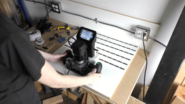
The first video below is mostly her talking through her design process, materials choices, and ideas about fabricating the somewhat intricate pieces of the latch. All 44 makers involved in the project get to choose what materials and methods they’ll use to make their parts, and [Fran] decided to use wood. Her first inclination was to use oak and brass, a nice combination with an 80s vibe, but in the second video, which covers more of the initial fabrication, she explains her switch to walnut. Unfortunately, the only CNC option she has is a Shaper Origin, which presents some difficulties; the handheld tool requires some complicated fixturing to safely machine the small parts needed, and its inability to read STL files means that [Fran] is stuck with a complicated software toolchain to drive the tool.

There are more videos to come as [Fran] gets further into the build, and we’re looking forward to seeing how her part and the rest of the makers’ builds come out.

Continue reading “Project Egress: [Fran] Makes A Latch”

Solder Stencil

How To Laser Cut Mylar Solder Stencils

When you think about the difficulties of working with surface mount components, the first thing that often comes to mind is trying to solder those tiny little parts. Instead of soldering those parts by hand, you can actually apply solder paste to the pads and place all of the components on at once. You can then heat up the entire board so all of the parts are soldered simultaneously. It sounds so much easier! The only problem is you then need a solder stencil. You somehow have to get a thin sheet of material that has a perfectly sized hole where all of your solder pads are. It’s not exactly trivial to cut them out by hand.

[Juan] recently learned a new trick to make cutting solder stencils a less painful process. He uses a laser cutter to cut Mylar sheets into stencils. [Juan] appears to be using EagleCAD and Express PCB. Both tools are available for free to hobbyists. The first step in the process is to export the top and bottom cream layers from your CAD software.

The next step is to shrink the size of the solder pads just a little bit. This is to compensate for the inevitable melting that will be caused by the heat from the laser. Without this step, the pads will likely end up a little bit too big. If your CAD software exports the files as gerbers, [Juan] explains how to re-size the pads using ViewMate. If they are exported as DXF files, he explains how to scale them using AutoCAD. The re-sized file is then exported as a PDF.

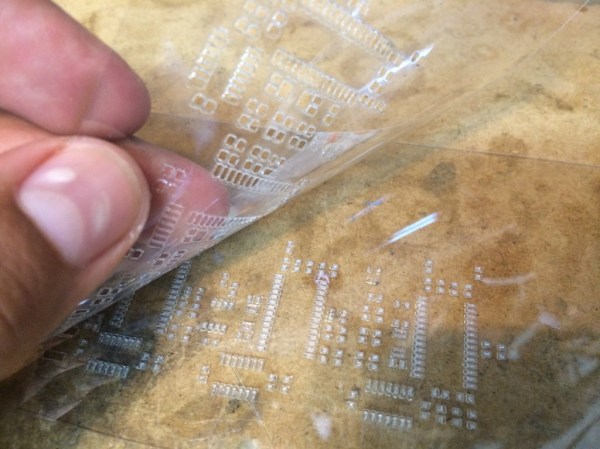
[Juan’s] trick is to actually cut two pieces of 7mil Mylar at the same time. The laser must be calibrated to cut all the way through the top sheet, but only part way into the bottom piece. The laser ends up slightly melting the edges of the little cut out squares. These then get stuck to the bottom Mylar sheet. When you are all done cutting, you can simply pull the sheets apart and end up with one perfect solder stencil and one scrap piece. [Juan] used a Full Spectrum 120W laser cutter at Dallas Makerspace. If you happen to have this same machine, he actually included all of the laser settings on his site.

3D Printering: Making A Thing In AutoCAD, Part II

printering

It’s time once again for another part in 3D Printering’s series of Making A Thing. Last week was a short tutorial on the beginnings of making a thing in AutoCAD. This is an extremely complex software package, and in a desire to make things short and sweet, I broke this AutoCAD tutorial into two parts.

Since we already covered the 2D design portion of AutoCAD, part II of this tutorial is going to turn our 2D part into a three-dimensional object. Check out the rest of the tutorial below.

Continue reading “3D Printering: Making A Thing In AutoCAD, Part II”

3D Printering: Making A Thing With AutoCAD, Part I

printering

Octopodes and useless plastic baubles begone. It’s time yet again for another installment of learning how to make a thing with 3D design tools. This week, we’re making something with AutoCAD. It’s an amazing piece of software that costs $4000 per seat. Hilariously expensive for any home tinkerer, but if you go to a university with an engineering program, there’s a computer lab with machines running AutoCAD somewhere on campus.

Last week we took a look at making something with OpenSCAD. AutoCAD is much, much different. Where OpenSCAD is sorta, kinda like programming, AutoCAD is just a digital version of t-squares, triangles, straight edges, and people getting uppity when you don’t call their drawing device a ‘lead holder’.

I’ve broken this tutorial down into two parts: right now you’re reading the tutorial on drawing 2D objects in AutoCAD. This weekend I’ll publish the transformation of 2D objects into a 3D printable part. Read on for how to create a 2D object in AutoCAD.

Continue reading “3D Printering: Making A Thing With AutoCAD, Part I”

On Not Proving The Twin Prime Conjecture With AutoCAD

As an HVAC engineer by trade, [Carlos Paris] spends a lot of time in AutoCAD designing all those hidden pipes, tubes, and ducts hidden in a building’s rafters. One day, [Carlos] read of an open contest – the prize was over a million dollars – to generate a prime number with a billion digits. [Carlos] misheard this as, ‘a prime number greater than one billion’ and of course said this was a trivially easy task and opened up his favorite tool – AutoCAD – in an effort to discover the largest prime ever. [Carlos] never generated a remarkably large prime, but he did come up with a very, very cool visualization of prime numbers on a number line, as well as a great justification of the twin prime conjecture, a problem in mathematics that has remained unsolved for several generations.

[Carlos] started his investigations into the properties of prime numbers by drawing a series of circles on a number line in AutoCAD. These circles were of diameters of all the integers, and going down the number line, these circles started to have an interesting, chaotic pattern (see above picture). [Carlos] found that whenever two circles intersected, that position was a prime number. It’s really nothing more than a Sieve of Eratosthenes, but it’s a very cool-looking visualization nonetheless.

Looking deeper into his graph, [Carlos] discovered there were certain primes that had another prime number just two places down the number line. For example, the numbers 3 and 5, 29 and 31, and 41,and 43 are twin primes, as the difference between the primes is only 2. The idea there are infinitely many twin primes is a famous unsolved problem in mathematics – it’s obvious it must be true, but no mathematician has yet come up with a proof of this conjecture.

[Carlos] looked at his number line and simplified it to a generic prime number. By taking a generic number line and overlaying the multiples of other prime numbers on this graph, [Carlos] had a very, very clever way of understanding exactly how twin primes come into existence.

In the end, [Carlos] is no closer to proving the twin prime conjecture than anyone else. We’ve got to hand it to him, though, for nerding out with an engineer’s favorite tool – AutoCAD – and managing to derive some fairly obscure mathematics on his own.

After the break you can see [Carlos]’s videos describing the though process that went into his creation. Very, very cool work.

Continue reading “On Not Proving The Twin Prime Conjecture With AutoCAD”