SD cards are great inexpensive storage for your embedded project. Using SPI, they only take a few wires to hook up, and every micro-controller has a FAT file system interface to drop in your project. Problem with SD cards are the connectors.
Usually connectors cost more than the brains of your project, and the friction fit, spring loaded contacts are not ideal for temperature swings, humidity and high vibration applications. Wouldn’t it be nice if you could just solder the thing down, especially if you know you are never going to remove it?
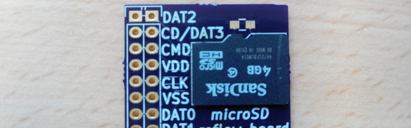
[Timothée] decided to try and succeeded in reflow soldering a Micro SD card direct to a breakout board. While starting as a what if experiment, the PCB was laid out in Ki-Cad and sent off to a fab. Once returned the Micro SD was fluxed, tinned and fluxed again, then reflowed using an IR setup.
The end result is a handy breakout board where you never have to worry about someone swiping the card to jam in their camera, and is ready for any breadboard project.


Very cool idea. I don’t have a reflow oven but will have to try this with a hot air rework station.
Very interesting, but the cheaper Micro-SD socket one can find is the SD/MMC adapter that is bundled in the same package of the Micro SD. Why not reflow solder the adapter instead?
Regards!
Probably because it’s bigger, the contacts are recessed from the surface, and the aforementioned worries about the contact reliability in somewhat-hostile environments. Probably a great thing if you’re at the perfboard-prototyping stage, though!
Well at least you would have the option to replace a dead/failed MicroSD with less trouble.
There’s no reason to believe the SD would fail any more than any other component on the board in which case if you were worried you’d be socketing all the chips.
Kingston SD cards fail all the time. Sandisk are the way to go.
“and the friction fit, spring loaded contacts are not ideal for temperature swings, humidity and high vibration applications.”
For a simple home project, yes, you can just use the included adapter. If you are looking to make it survive more extreme environments, this is a better option.
I think that normally the contacts are slightly recessed on those, with ridges between them, meaning it’s hard to reflow those.
“Usually connectors cost more than the brains of your project, and the friction fit, spring loaded contacts are not ideal for temperature swings, humidity and high vibration applications.”
If you’re looking for a cheap way to interface to a full size SD card, a standard dual row header at .1″ and some tape will get you there. not the most reliable, but dirt cheap.
Epic. Saved, thanks Timothée!
Nothing to say but “good idea”. I wonder if any company does this for commercial products? SD cards must be the cheapest way to get hold of flash memory.
I’ve never seen an actual MicroSD card, but eMMC is a thing – that’s an SD card in a more standard IC package like a BGA, with a slightly wider interface (8 bits instead of 4) because more pins are available (although you can talk to them in single/SPI and 4 bit modes too).
eMMCs are very common in phones – they’re much less of a pain than NAND flash, you can use any filesystem you like instead of specific NAND-aware ones like JFFS and YAFFS that are aware of NAND vagaries like bad blocks and wear levelling.
The Raspberry Pi Compute Module also uses an eMMC, although this is just because they already have an MMC interface which is used for the SD card so it minimises software effort on their part.
eMMCs are way more reliable than SD cards. They also work fine in 1 bit, but not all of them have SPI.
While the SPI interface is required by the SD spec, it can also be absent from cheaper SD cards.
eMMC chips implement the MMC spec not the SD. The MMC spec is related to teh SD one but there are some small differences.
I have opened usb sticks which were just a micro sd surface soldered to the board and a comtroller chip. The micro sd did have extra contacts tho no idea what they did
This is epic level awesome. Absolutely adding this layout to my next board instead of trying to dink around with those sockets.
There is a big assumptions that the microSD card can handle reflow temperature and that it would apply to all the consumer cards from different manufacturers…
The SD card will have gone through at least one reflow cycle already in its life to get the components on the substrate. Typically these components are also rated for a minimum of two reflow cycles.
As a hack, it’s a pretty good idea. As a production product…..certainly doable for consumer electronics so long as a proper reliability study is done.
To elaborate on Northerndiy’s answer – all SMD components are rated for at least two reflows because you need to reflow twice to populate both sides of the board!
“reflow cycle” here refers to a properly profiled thermal cycle that minimises stress, which is nowhere near as stressful as rework with some sort of heat gun, but in practice it’s not normally an issue.
The bare dies are wired bonded in a microSD, so your comments really do not apply as they are not SMD parts. My URL to bunnie’s blog shows exactly what’s inside which agrees with what I have said.
Even if the parts are soldered down like inside some of the larger SD cards, the casing/molding compound that is put on *after* the reflow assembly do not need to handle the temperature.
So like all things that are engineered/manufactured, me of the manufacturers might choose to use a cheaper material when they don’t need to handle the reflow temperature. And of course these things are made all over the place or even OEM from different suppliers/factories, you have no idea what your next batch is going to be like.
I’m confident they can.
You are making a very wrong assumption that the SD cards have individual packages soldered down.
The chips are die size packages wire bonded onto a substrate and unknown epoxy packing material that may or may not handle reflow temperature.
See here for what a MicroSD looks like inside.
http://www.bunniestudios.com/blog/?page_id=1022
Holy crap… I bought a lot of Kingston over the years….
Looks like I’m going elsewhere….
Not all Kingston cards are bad in fact I find most Kingston cards to be very reliable. The issue lies in insuring the card you receive is genuine something easier said then done at times. All electronics have the issue of counterfeit parts in the supply chain the best you can do is be vigilant.
It all depends on where you are buying it. If you are buying it from legit big box store chains outside of Asia, you are probably safe. The stores buyers buy in bulk and would likely screen the suppliers. If the stuff they sell are counterfeits, they have a lot more to lose. They also have better replace policies.
I have bought some 32GB SD and MicroSD cards from a big sale in a big box store that are around similar pricing as the usual Chinese mail order places.
So this is the poor mans eMMC?
Wow, this is fantastic!
sounds good UNTIL you get flash errors. and then what? flash cards are not that reliable and soldering it down sounds pretty bad to me.
if the memory were much more reliable, then ‘good idea’ but I simply could not trust an sd card or thumbdrive.
now, if there was a redundant format, THAT would be killer! solder both down and as long as they are mirrored, you are good to go. anyone have any ideas on how to raid-1 (lol) the sd cards in a cheap and easy way?
Solder it on a piece of PCB with a standard pin connector then, problem solved. If it breaks, make a new one and press it in.
Addendum: And as you see on the picture above the article, that’s basically what this is, a small PCB with it soldered on, which you can replace.
One question I’ve not seen a good answer to:
How do you detect/repair a bad filesystem on a small microcontroller and a big SD card ?
Take the SD card out and mount it on a PC and use PC file recovery programs. Hopefully you are using a journal file system that are easier for file recovery. That is assuming that the corrupted file system can be access.
But after you solder down the SD card, like in this project, that won’t work.
A journalled filesystem is an interesting idea, but is it feasible on a small (e.g. < 64 KB RAM) and slow (e.g. 20 Mbps SPI) system ?
Go get a cheap USB SD adapter. Remove the socket. Replace with female pin headers that match up to your breakout. Now it should work just fine! Just make sure you break out all the pins, not just the ones used for SPI and make sure to use the same pinout for every breakout you make.
If you have to go through the trouble of recovering your data, you are already too late and trying to fix things after the fact. May be you should either have a more reliable system (firmware, power backup, a better file system) or a much better way of socketing the SD. More on the line suggested by [Me]. Tristate the microcontroller I/O to the SD, and run the signals to a breakout or connector for an external reader to read the content.
Using a PC to recover the data is the correct approach. The huge memory allow a much larger buffering and better algorithm for recovery. Someone might already written a recovery program for the file system. Last thing you want to do is to have every embedded system to have a large piece of recovery code that rarely needed.
Love it only thing different i would do or add i should say is I would add a dab of hot glue to make sure it stays.
This defeats the whole point of being able to remove the SD card and stick it in your PC.
If you need non-removable memory, just use a flash IC.
Large flash ICs with simple interface are rare, and typically BGA.
And you can still preload images from PC before soldering.
Sorry for the pointless post but the OCD in me is bothered by the longer pads not being in the right placement for the SD card when it’s the right way up.
Looks like potential issues over-weights benefits.
Let me summarize what others have pointed out about the problems:
1. Can’t remove the card to do any type of repair that needs a computer.
2. Reflow is a big question mark. Do you even have the reflow curve of your card?
If I go just a few degrees over in reflow, some of my cheaper plastic parts start to deform. Battery holders, sd card holders, etc. It only takes a minimal amount of deformation to destroy a micro sd slot. The latch will not engage etc. Can’t imagine what may happen to a micro sd CARD that is entirely plastic. I’m not an engineer but will reference the age-old question: have you checked the spec sheet yet?
Vibration, moisture, reliability of socket, etc…
If you have these same problems to solve but want to retain the ability to remove or swap the chip in a standard socket I’m thinking you could…
Mount the socket inside the chasis. If removal is only a rare event for repair or upgrade then why expose it to the outside?
Put a small piece of tape over it. That should solve the vibration issue.
Put a big piece of tape over it. Use a piece big enough to cover the whole socket + chip and now you are keeping dust out too. I wouldn’t dunk it in water but I would imagine it would be pretty reisitant to humidity or even occasional drops of liquid too.
As for reliability of the socket itself… well.. bein internal and covered in tape you will not be too tempted to insert/remove it on a regular basis. I would expect it to last a long time!
I’ve never seen SD cards done this way but I sure have seen this done with CF cards used as hard drives for embeded computers.
“Problem with SD cards are the connectors. Usually connectors cost more than the brains of your project”
I’m pretty sure that cost is not the point: the dude paid $4.1 for a custom PCB, which is definitely more than a connector. Never mind that you need to have a IR reflow kit!
I’m not arguing with the rest of the article, but the cost aspect is moot.
From a production perspective, it is, you are only focusing. 10ct x 1k units does cost.
Sockets are expensive? $0,08 doesn’t seem too much. http://www.aliexpress.com/item/10X-Electrical-Sockets-TransFlash-TF-Micro-SD-Card-Self-eject-Socket-Plug-Free-Shipping/1885383571.html
The swing-lid style (like many SIM holders) connectors that cost 50 cents seem to be pretty robust, and are very small. Way better than just soldering the thing down.
Hmmm.
I am thinking a possible improvement on this idea. Not FULL deadbug but…
When one orders PCB from a fab house; can they remove say 1-3 layers of FR4 on a corner or side, so the MicroSD card would be completely flush with the PCB?
That might make it possible to have a thin nylon/FR4 latch to keep it clamp connected.
It can be done as multilayer boards are built up of laminated double side layers. The board house will charge you extra for it. It can be tricky for PCB panels.